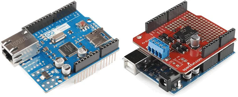
An Arduino shield PCB is an expansion board for use with Arduino boards like Uno, Nano, and Mega. It provides functions like Wi-Fi, motor control, connecting sensors, and relay control. You can buy the standard Arduino shield PCBs designed and produced by the Arduino company, or you can design your custom Arduino shield PCB and have them manufactured by the PCB manufacturers.
Custom Arduino shield PCBs are tailored to your project requirements and allow you to brand the devices for marketing. In this blog, you can explore how to build a custom Arduino shield PCB.
In this article:
Part 1. Learn about Custom Arduino Shield PCB Part 2. Steps of Designing a Custom Arduino Shield PCB Part 3: One-stop Arduino Shield PCB and PCBA Manufacturer PCBONLINELearn about Custom Arduino Shield PCB
A custom Arduino shield PCB is a printed circuit board (PCB) with the same pin layout and size as the base Arduino board you have chosen. These shields are useful components that easily attach to an Arduino board by stacking on them, adding more functionality without requiring excessive wires.
Custom Arduino shields are highly versatile and find applications in various fields. The applications of custom Arduino shields include:
- Internet of Things (IoT): Adding Wi-Fi, Bluetooth, or LoRa modules to control smart devices.
- Robotics: Simplifying motor and servo control.
- Agriculture: Monitoring soil moisture, temperature, and other parameters.
- Medical devices: Integrating sensors for vital monitoring systems.
- Home automation: Implementing smart switches and sensors.
Steps of Designing a Custom Arduino Shield PCB
Before starting the design of your custom Arduino shield, it is essential to research the Arduino pin layout and identify the components required for your project. For example, when designing a shield for the Arduino Uno, you need to familiarize yourself with its headers for digital I/O, analog inputs, power, and communication interfaces.
Step 1: Define the purpose
The first step in designing your custom Arduino shield PCB is to define its purpose clearly. Will it be used to control motors, read sensor data, or provide wireless connectivity? Understanding the shield's purpose will help you determine the required components and layout.
Additionally, you need to consider whether the shield will be a one-time-use solution or if it needs to be adaptable for future projects. If scalability is a requirement, consider adding extra connectors or useful features to extend its functionality.
Step 2: Choose design software
The next step is to select a suitable PCB design software. There are many options available, ranging from free and basic to paid and advanced software tools. Some popular choices include EasyEDA, Proteus, KiCad, and Altium Designer. When selecting software, consider the following factors:
- Library support: Accessing pre-designed components from libraries can save a lot of time.
- Simulation capabilities: Being able to simulate your circuit helps identify potential issues early in the design phase.
- 3D visualization: Visualizing your PCB in 3D ensures proper fit and improves the aesthetics of your design.
Step 3: Create the schematic
To create a schematic, you will first need to add the elements like resistors, capacitors, ICs, and connectors that are needed within the circuit to your software workspace as illustrated in the next image.
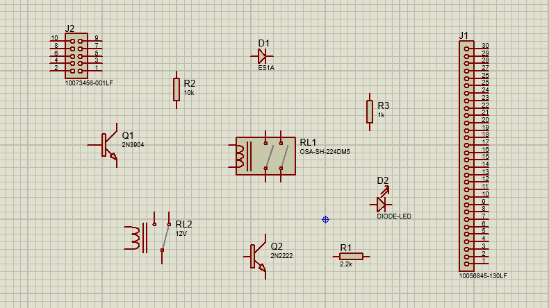
Construct the required circuit using the gathered components. Do not forget to label the wires and components for later use and always cross-check the final schematic for any errors.
After completing the circuit diagram using the right values of components like resistors, capacitors, etc, add headers suitable for Arduino, these will help stack your board on top of the Arduino board.
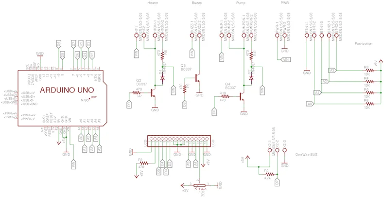
An Arduino Uno shield's schematic typically looks like the following image, with connections to and from the Arduino board, additional headers, and all other components.
Step 4: Design the PCB layout
Once your schematic is complete, convert it into a PCB layout. Start by defining the dimensions based on the Arduino specification sheet to ensure your shield is compatible with the chosen Arduino board.
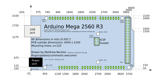
For instance, the dimensions of an Arduino Mega board are provided in the next image (specified in mils) giving a clear idea of where to place components and headers for stacking.
Place the components strategically to minimize the length of connecting tracks and prevent clutter. Include a ground plane to reduce noise and enhance stability. Additionally, add a silkscreen layer to help with the assembly process or debugging if issues arise.
While designing the layout, follow these important routing guidelines:
1. Use appropriate trace widths to handle the expected current and prevent overheating.
2. Avoid 90-degree bends in traces; opt for 45-degree bends to maintain signal integrity.
3. Place decoupling capacitors as close as possible to IC power pins to stabilize the power supply and filter noise.
4. Minimize loop areas for critical signals to reduce electromagnetic interference (EMI).
5. Keep high-speed and low-speed signal traces separate to avoid cross-talk.
6. Use ground and power planes effectively to reduce noise and maintain power stability.
7. Avoid crossing analog and digital signal lines to minimize noise interference.
8. Minimize the use of vias to reduce inductance and maintain signal quality.
Step 5: Validate the design
After routing is complete, perform a Design Rule Check (DRC) using your PCB design software. This step ensures compliance with manufacturing standards. Pay attention to trace clearances, verify there are no floating traces, and ensure that the shield dimensions and pin layout match the Arduino board.
Step 6: Export and order the PCB
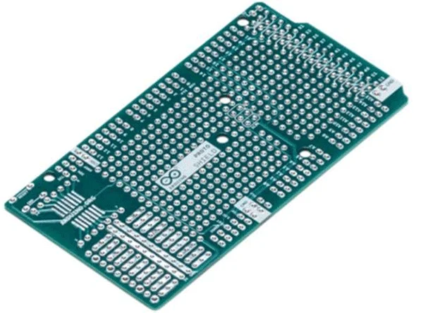
Once your design passes validation, generate Gerber files and select a reliable PCB manufacturer like PCBONLINE, which has strong one-stop PCB and PCBA capabilities. Submit your Gerber files to the PCB manufacturer to place an order for your custom shield. Your manufacturer PCBONLINE will provide you with the final PCB for your Arduino board, just like the one shown in the next image (of Arduino Mega.)
Step 7: Arduino shield PCB assembly
When the custom shield PCB is ready, you can start the PCB assembly. If your board quantity is small and relatively simple, you can use the silkscreen layer as a guide to correctly place components, then solder them in place by hand.
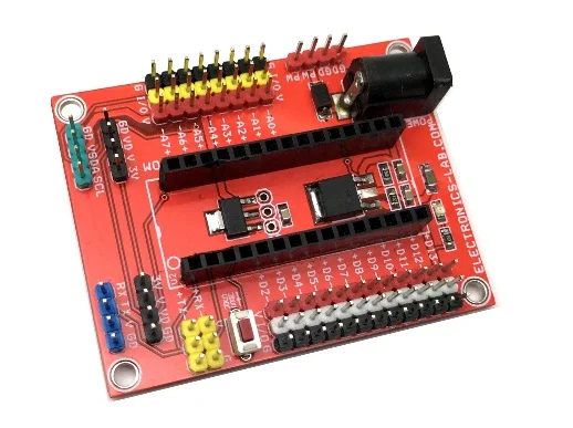
However, if your project serves business purposes, you can let the one-stop PCBA manufacturer PCBONLINE assemble the PCBs by SMT and THT assembly methods, test the boards, and do the value-added services such as conformal coating, IC programming, and even box-build assembly until the delivery of the final devices.
One-stop Arduino Shield PCB and PCBA Manufacturer PCBONLINE
PCBONLINE is a one-stop PCBA manufacturer for Arduino shields and middle to high-end applications, such as automotive, aerospace, defense, industrial, medical, communication, computer, and consumer electronics.

Founded in 1999, PCBONLINE has two large advanced PCB manufacturing bases, one PCB assembly factory, stable supply chains, and an R&D team.
PCBONLINE has turnkey PCB and PCBA manufacturing capabilities for Arduino shields and other applications, including R&D, prototyping/sampling, PCB fabrication, component sourcing, PCB assembly, PCBA value-added, and box-build assembly.
PCBONLIINE provides free design for manufacturing (DFM) and one-on-one engineering support for your custom Arduino shield PCB project.
High-quality PCB and PCBA manufacturing certified with ISO 9001:2015, ISO 14001:2015, IATF 16949:2016, RoHS, REACH, UL, and IPC-A-610 Class 2/3.
As a source factory manufacturer, the PCB and PCBA manufacturing is cost-effective without hidden price items.
Once your PCBA project goes to the bulky production stage, PCBONLINE refunds the fees of R&D, prototyping/sampling, and PCBA functional testing.
No matter what quantity of boards you want, you can let PCBONLINE work for your custom Arduino shield PCB and other projects from prototype to PCBA and finished device. To get a quote for your project, please contact info@pcbonline.com.
Conclusion
Custom Arduino shield PCBs for Arduino boards eliminate the limitations of breadboards and excessive wiring, making your designs cleaner and more efficient. Designing a custom Arduino shield PCB is both a technical and creative process. By following the steps and guidelines outlined in this article, you can create a high-quality PCB shield tailored to your project's specific needs. If you have questions about your project, chat with PCBONLINE from the online chat window.
PCB assembly at PCBONLINE.pdf


