
Hydroponics is a soilless method of growing plants that efficiently uses water, space, and nutrients. Combined with the ESP32 microcontroller, we can build a smart hydroponics system that automates plant care and maximizes yield.
This blog will walk you through the steps to design, build, and program a small hydroponics system using an ESP32. We'll also discuss the smart hydroponics system components, schematic design, and PCB creation.
In this article:
Part 1. What Is a Smart Hydroponics System? Part 2. Components and Software for Building the Smart Hydroponics System Part 3: Step-by-Step Guide to Build the Example Smart Hydroponics System Part 4: Schematic Design of the Example Smart Hydroponics System Part 5: PCB Design for Smart Hydroponics Systems Part 6: One-stop PCBA Manufacturer for Smart Hydroponics SystemsWhat Is a Smart Hydroponics System?
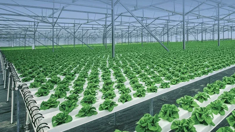
A hydroponics system grows plants in water enriched with nutrients instead of soil. The smart hydroponics system involves controlling pH, nutrient levels, temperatures, and humidity. The ESP32 microcontroller is a perfect MCU for this application due to its Wi-Fi capability, multiple GPIO pins for sensors and actuators, and low power consumption.
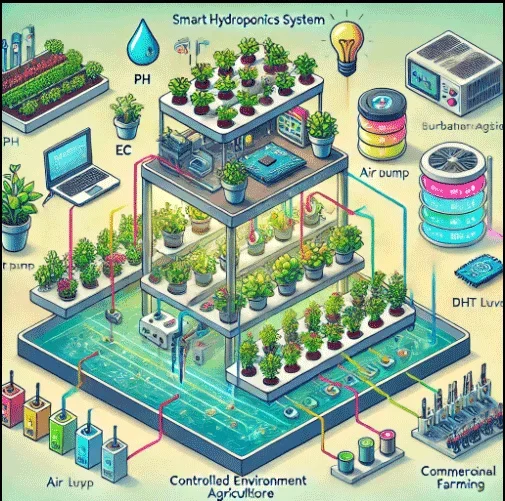
Smart hydroponics systems are widely used in:
- Urban agriculture: Growing plants in limited spaces like apartments or rooftop gardens.
- Controlled environment agriculture (CEA): Indoor farming with controlled environmental conditions.
- Education: Demonstrating sustainable farming techniques to students.
- Commercial farming: Large-scale vegetable and herb production.
- Research: Testing new plant varieties or studying growth patterns under specific conditions.
Components and Software for Building the Smart Hydroponics System
The hardware components required for creating the simple smart hydroponics system in this blog are below.
- ESP32 Microcontroller: Acts as the brain of the system.
- Water pump: Circulates the nutrient solution.
- Air pump with air stone: Provides oxygen to plant roots.
- Water level sensor: Monitors water levels.
- pH sensor: Measures the acidity or alkalinity of the nutrient solution.
- EC sensor: Tracks nutrient concentration in the water.
- DHT22 sensor: Measures air temperature and humidity.
- LED grow lights: Provide artificial light for plant growth.
- Relay module: Controls the pumps and lights.
- Power supply: Provides power to the ESP32 and peripherals.
- Plant pots and container: Holds the plants and water solution.
The software required for building this smart hydroponics system project includes:
Arduino IDE - to program the ESP32.
Libraries - for sensors like DHT, pH, and EC.
IoT platform - for remote monitoring (e.g., Blynk, Arduino IoT Cloud, or ThingSpeak).
Step-by-Step Guide to Build the Example Smart Hydroponics System
Below are the steps of how to build the smart hydroponics system example.
Step 1: Plan the system design
Choose the type of hydroponics system (e.g., Deep Water Culture).
Determine the placement of components like pumps, sensors, and grow lights.
Step 2: Set up the hardware
ESP32 connections:
- Connect the water level sensor, pH sensor, EC sensor, and DHT22 to the ESP32 GPIO pins.
- Connect the relay module to control the water pump, air pump, and grow lights.
System layout:
- Place plant pots in a container with holes for the roots to dangle into the nutrient solution.
- Insert the air stone and water pump into the container.
Step 3: Write the ESP32 code
Use the Arduino IDE to program the ESP32. Here's a brief overview of the functionality:
- Read sensor data (pH, EC, temperature, humidity, and water level).In the given example we only use temperature and humidity sensors.
- Automate pumps and lights based on sensor readings and preset thresholds.
- Send data to a cloud platform for monitoring and control. You can use the platform according to your choice.
Code Example:
#include
#include
#define DHTPIN 2
#define DHTTYPE DHT22
#define WATER_PUMP_PIN 5
#define AIR_PUMP_PIN 18
#define LIGHT_PIN 19
DHT dht(DHTPIN, DHTTYPE);
void setup() {
Serial.begin(115200);
dht.begin();
pinMode(WATER_PUMP_PIN, OUTPUT);
pinMode(AIR_PUMP_PIN, OUTPUT);
pinMode(LIGHT_PIN, OUTPUT);
WiFi.begin("yourSSID", "yourPASSWORD");
while (WiFi.status() != WL_CONNECTED) {
delay(1000);
Serial.println("Connecting to WiFi...");
}
Serial.println("Connected!");
}
void loop() {
float temp = dht.readTemperature();
float hum = dht.readHumidity();
// Example logic for controlling pumps and lights
if (/* water level is low/you can use logic as you want */) {
digitalWrite(WATER_PUMP_PIN, HIGH);
} else {
digitalWrite(WATER_PUMP_PIN, LOW);
}
delay(10000); // Adjust as needed
}
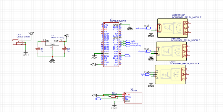
Schematic Design of the Example Smart Hydroponics System
Below is a basic schematic design for the hydroponics system:
1. ESP32 GPIO connections:
- DHT22 to GPIO4
- Water pump relay to GPIO5
- Air pump relay to GPIO6
- Light relay to GPIO7
2. Power supply:
- Use a 5V/2A adapter to power the ESP32 and relays.
Sensors:
- Connect pH and EC sensors to analog pins on the ESP32.
|
Component
|
ESP32 Pin
|
|
DHT22 Sensor
|
GPIO4
|
|
Water Pump Relay
|
GPIO5
|
|
Air Pump Relay
|
GPIO18
|
|
Grow Light Relay
|
GPIO19
|
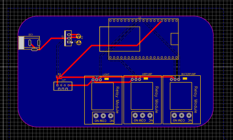
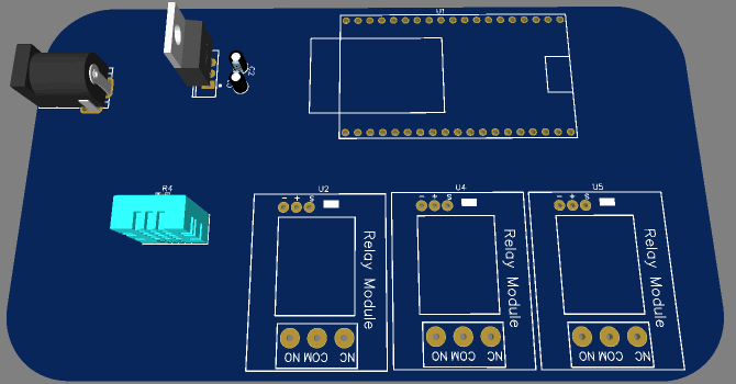
PCB Design for Smart Hydroponics Systems
To build any smart hydroponics system, you will need to design the PCB for it. A PCB ensures reliability, reduces wiring clutter, and makes the system compact. You can use the PCB design software like KiCAD or Easyeda to design your PCB.
The steps to design the PCB are below.
Create the schematic:- oPlace ESP32, relay modules, and sensor connectors in the schematic editor.
- Add connections as per the schematic design.
- Arrange components logically to minimize trace lengths.
- Use ground planes to reduce noise.
- Ensure proper spacing between high-power and low-power components.
- Generate Gerber files for manufacturing.
Example PCB Layout Features:
- Headers for sensors: Use screw terminals for easy sensor connections.
- Relays: Place near the edges for easy wiring.
- Power input: Include a barrel jack or USB-C connector for power.
The enhancements and future work that can add to the PCB design can be:
- Add a camera module for monitoring plant growth.
- Include AI-based growth predictions using TensorFlow Lite.
- Integrate a solar panel for off-grid operation.
After completing the design, you can order PCBA manufacturing services from PCBONLINE for manufacturing. PCBONLINE provides one-stop PCBs for smart hydroponics systems and any other IoT systems.
After PCB fabrication, PCBONLINE assembles the components on the PCB, installs the PCBA in a waterproof enclosure near the hydroponics system, and tests the PCBA before running the complete setup of the hydroponics system.
One-stop PCBA Manufacturer for Smart Hydroponics Systems
If you want to develop and manufacture a smart hydroponics system under your brand or your company name, work with the one-stop IoT PCBA manufacturer PCBONLINE with R&D and turnkey electronics manufacturing under one roof.
Founded in 1999, PCBONLINE has two large advanced PCB manufacturing bases, one PCB assembly factory, stable supply chains, and an R&D team. Besides, it has long-term cooperation with China's top 3 mold and enclosure factories for jigs and enclosures for PCB assembly and box-builds. What's more, PCBONLINE has strategic cooperation with mainstream microcontroller companies such as Espressif, Neoway, and Quectel.
PCBONLINE provides free design for manufacturing (DFM) and one-on-one engineering support for smart hydroponics systems and any IoT projects.
PCBONLINE has IoT project R&D capabilities and can do the R&D for your smart hydroponics system project or take part in your project's development from the early stage.
No worries about programming the MCU, as the one-stop PCBA manufacturer PCBONLINE offers free IC programming for you.
The IoT PCBs, PCBAs, and box-builds at PCBONLINE have gone through comprehensive tests, such as functional testing, 3D AOI, and application simulation testing.
High-quality IoT PCBA manufacturing certified with ISO 9001:2015, ISO 14001:2015, IATF 16949:2016, RoHS, REACH, UL, and IPC-A-610 Class 2/3.
When your smart hydroponics system and any other IoT project go to bulky production, PCBONLINE refunds the fees of R&D, sampling, and PCBA functional testing. To get a quote for your MQTT IoT PCBA project, contact info@pcbonline.com.
Conclusion
This article uses an example project to demonstrate how you can build a smart hydroponics system. By integrating IoT platforms, you'll have full control and insights into your system from anywhere. To develop and manufacture smart hydroponics systems and any other IoT devices, work with professional manufacturers like PCBONLINE to provide one-on-one engineering support and turnkey manufacturing.
PCB assembly at PCBONLINE.pdf


