
The Controller Area Network (CAN) protocol is a robust communication protocol widely used in automotive, industrial, and embedded systems. It allows multiple microcontrollers to communicate efficiently without a host computer.
In this blog, we will explore CAN communication, its applications, CAN bus messages, and how to interface an ESP32 with an MCP2515 CAN controller module for real-world projects. We will also discuss the schematic design and PCB design considerations.
In this article:
Part 1. Understanding the CAN Protocol and Its CAN Frames Part 2. CAN Communication Using ESP32 and MCP2515 One-Stop PCBA Manufacturer for IoT CAN Protocol ProjectsUnderstanding the CAN Protocol and Its CAN Frames
The Controller Area Network (CAN) is a multi-master, message-based protocol designed for efficient and reliable data transmission between multiple nodes. Bosch originally developed the protocol in the 1980s and is now a standard in many industries.
The key features of the CAN protocol are:
- Multi-master communication – Any node can initiate communication.
- Collision handling – The protocol resolves conflicts based on message priority.
- Error detection and correction – Built-in CRC (Cyclic Redundancy Check) ensures reliable transmission.
- High-speed communication – Supports baud rates from 10 kbps to 1 Mbps.
- Long-distance communication – Can transmit data over long distances with proper termination resistors.
To understand the Controller Area Network (CAN) protocol thoroughly, you should learn about the CAN frame. It is a fundamental data unit in the CAN protocol. It consists of various fields that help in message identification, error detection, and efficient communication.
Types of CAN Frames
The CAN protocol defines four types of frames:
- Data frame – Carries actual data from one node to another.
- Remote frame – Requests data from another node.
- Error frame – Signals a communication error.
- Overload frame – Used for delay and synchronization.
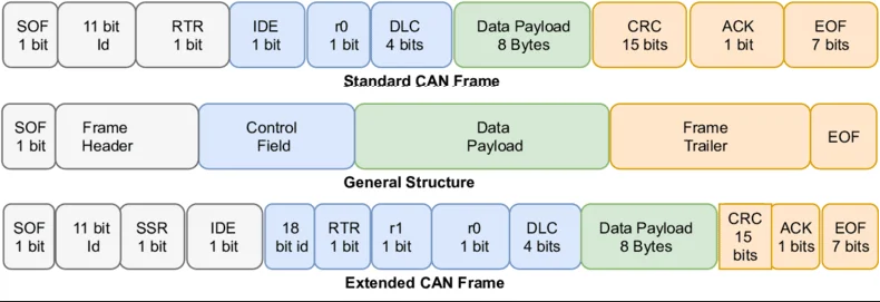
Structure of a Standard CAN Frame (11-bit Identifier)
A CAN data frame consists of multiple fields, as shown below:
| SOF | Identifier | RTR | IDE | DLC | DATA | CRC | ACK | EOF |
1. Start of frame (SOF)
- 1-bit
- Indicates the beginning of a new CAN frame.
- Synchronizes all nodes on the bus.
2. Identifier
- 11 bits (Standard CAN) or 29 bits (Extended CAN)
- Defines the priority of the message (lower value = higher priority).
3. Remote transmission request (RTR)
- 1-bit
- 0 → Data Frame
- 1 → Remote Frame (requests data)
4. Identifier extension (IDE)
- 1-bit
- Standard (11-bit) Identifier
- 1 → Extended (29-bit) Identifier
5. Data length code (DLC)
- 4 bits
- Specifies the number of bytes in the Data field (0 to 8 bytes).
6. Data field
- 0 to 8 bytes
- Contains the actual information being transmitted.
7. Cyclic redundancy check (CRC)
- 15 bits + 1 bit delimiter
- Used for error detection.
8. Acknowledge (ACK)
- 2 bits
- ACK slot: Receiver nodes send an acknowledgment.
- ACK delimiter: Always 1-bit.
9. End of frame (EOF)
- 7 bits
- Marks the end of the frame.
CAN Bus Message Example
Let's say an ESP32 is sending a temperature reading via CAN.
|
Field
|
Example Value
|
Description
|
|
SOF
|
0
|
Start of the frame
|
|
Identifier
|
0x100
|
Message ID
|
|
RTR
|
0
|
Data Frame
|
|
IDE
|
0
|
Standard ID
|
|
DLC
|
4
|
4 bytes of data
|
|
Data
|
0x1A 0x2B 0x3C 0x4D
|
Temperature Data
|
|
CRC
|
Computed Value
|
Error Check
|
|
ACK
|
1
|
Acknowledged
|
|
EOF
|
7 bits
|
End of Frame
|
This message represents a 4-byte temperature reading being sent with ID 0x100.
Standard vs. Extended CAN Frame
|
Feature
|
Standard CAN (11-bit)
|
Extended CAN (29-bit)
|
|
Identifier Bits
|
11 bits
|
29 bits
|
|
Message Priority
|
Higher (more efficient)
|
Lower
|
|
Payload
|
0-8 bytes
|
0-8 bytes
|
|
Common Usage
|
Automobiles, industrial systems
|
Complex networks, aerospace
|
Most automotive applications use Standard CAN (11-bit), while Extended CAN (29-bit) is used in advanced systems requiring more identifiers.
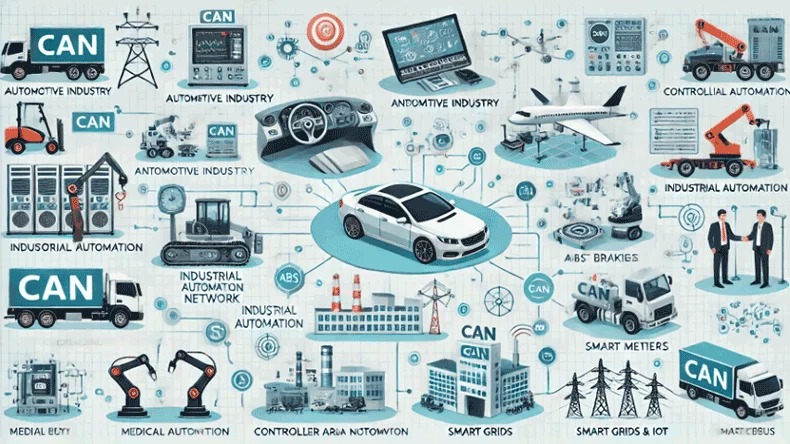
Applications of the CAN Protocol
The CAN protocol is widely used in:
- Automotive industry: Engine control units (ECU), airbags, ABS braking systems.
- Industrial automation: Factory automation, robotic systems.
- Medical equipment: Medical devices, and patient monitoring systems.
- Aerospace industry: Satellite communication, avionics.
- Smart grids & IoT: Sensor networks, IoT automation.
CAN Communication Using ESP32 and MCP2515
The ESP32 does not have a native CAN controller (unlike the ESP32-S3), so we use the MCP2515 CAN controller module with an external TJA1050 transceiver to enable CAN communication.
By following the steps in this guide, you can build ESP32-based CAN networks and take your IoT and embedded projects to become real products.
The components required include:
- ESP32 development board
- MCP2515 CAN controller module
- TJA1050 CAN transceiver
- 120Ω terminating resistor
- Jumper wires
- Power supply (5V)
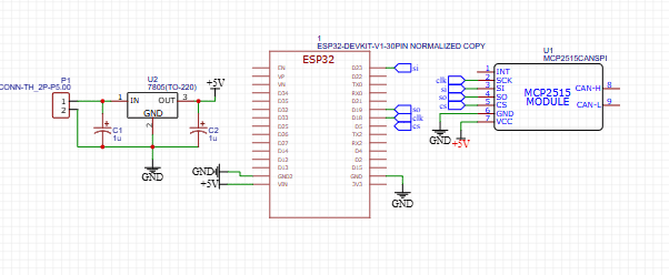
Circuit Diagram & Schematic Design
Below is the circuit diagram for interfacing ESP32 with MCP2515.
Pin Connections
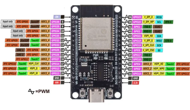
|
ESP32
|
MCP2515 CAN Controller
|
|
5V
|
VCC
|
|
GND
|
GND
|
|
GPIO23
|
MOSI
|
|
GPIO19
|
MISO
|
|
GPIO18
|
SCK
|
|
GPIO5
|
CS
|
|
GPIO21
|
INT
|
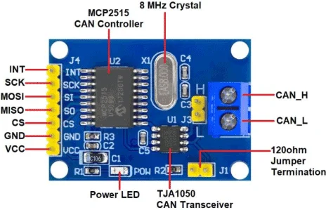
The schematic includes:
1. ESP32 connection: SPI communication with MCP2515.
2. MCP2515 CAN controller: SPI interface. oInterrupt pin for message reception.
3. 120Ω resistors: Placed at both ends of the CAN bus to prevent signal reflections.
Writing Code for CAN Communication in ESP32
To use MCP2515 with ESP32, we need the "mcp_can" library. Install it via the Arduino Library Manager.
Transmitter Code
The following ESP32 code sends CAN messages.
#include
#include
#define CAN_CS 5
MCP_CAN CAN(CAN_CS); // Set CS pin
void setup() {
Serial.begin(115200);
while (CAN_OK != CAN.begin(MCP_ANY, CAN_500KBPS, MCP_16MHZ)) { // Initialize CAN at 500kbps
Serial.println("CAN BUS Init Failed");
delay(100);
}
Serial.println("CAN BUS Initialized");
}
void loop() {
unsigned char message[8] = {0x01, 0x02, 0x03, 0x04, 0x05, 0x06, 0x07, 0x08};
CAN.sendMsgBuf(0x100, 0, 8, message);
Serial.println("Message Sent!");
delay(1000);
}
Receiver Code
The receiver listens for messages on the CAN bus.
#include
#include
#define CAN_CS 5
MCP_CAN CAN(CAN_CS);
long unsigned int rxId;
void setup() {
Serial.begin(115200);
while (CAN.begin(MCP_ANY, CAN_500KBPS, MCP_16MHZ)) {
Serial.println("CAN BUS Init Failed");
delay(100);
}
Serial.println("CAN BUS Initialized");
}
void loop() {
if (CAN_MSGAVAIL == CAN.checkReceive()) {
unsigned char len = 0;
unsigned char buf[8];
CAN.readMsgBuf(&rxId,&len, buf);
Serial.print("Received Message: ");
for (int i = 0; i < len; i++) {
Serial.print(buf[i], HEX);
Serial.print(" ");
}
Serial.println();
}
}
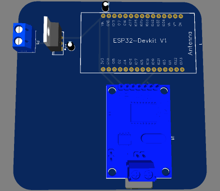
PCB Design for CAN Interface with ESP32
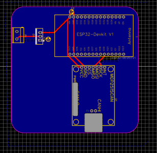
Designing a PCB for CAN communication ensures a reliable and noise-free operation. Here's how to do it:
1. Power distribution
Use a 5V regulator.
2. Signal routing
SPI traces (MISO, MOSI, SCK, CS) should be kept short and direct.
Keep a 120Ω termination resistor between CANH and CANL.
3. Ground plane
A solid ground plane is crucial for reducing noise.
Keep high-frequency components away from power lines.
4. Connector placement
Include DB9 or screw terminal connectors for external CAN devices.
One-Stop PCBA Manufacturer for IoT CAN Protocol Projects
If you want electronics manufacturing from R&D, PCB, to finished CAN-protocol IoT devices under one roof, you can work with the one-stop IoT PCBA manufacturer PCBONLINE.
Found in 1999, PCBONLINE has two large advanced PCB manufacturing bases, one PCB assembly factory, stable supply chains, and an R&D team for development and one-stop PCBA manufacturing for CAN-protocol IoT devices.
PCBONLINE has R&D capabilities and rich CAN-protocol IoT development experience. We can do the R&D or participate in your project's development from the early stages.
PCBONLINE offers free design for manufacturing (DFM) and one-on-one engineering support and solves all technical issues to ensure the smooth manufacturing process and successful results of your CAN-protocol IoT project.
Strong and one-stop automotive and IoT PCBA manufacturing capabilities custom meeting your requirements, including R&D, prototyping/sampling, PCB fabrication, component sourcing, PCB assembly, PCBA value-added, and IoT device box-build assembly.
The automotive industry components that PCBONLINE provides for PCB assembly are reliable and traceable. You can check our PCB certifications, including ISO 9001:2015, IATF 16949:2016, REACH (EC 1907/2006), RoHS (Directive 2002/95/EC), and UL.
As a source factory manufacturer for PCBA and CAN-protocol IoT devices, the electronics manufacturing from PCBONLINE is at reasonable prices without hidden costs.
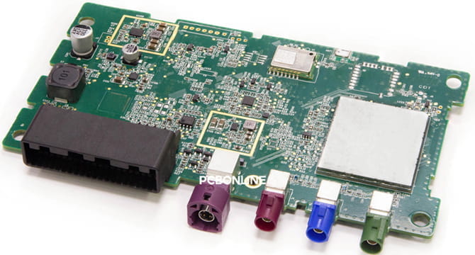
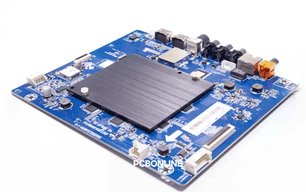
PCBONLINE has successfully worked on many CAN-protocol projects. For example, the below audio and video decoding PCBA with CAN communication. Because the FPGA chip will generate a lot of heat during operation, the black heat sink in the middle dissipates heat quickly to ensure that the core components of the board work stably and efficiently.
To get a quote for your CAN-protocol IoT PCBA project, please contact info@pcbonline.com. When your project goes to bulk production, we will refund the fees of R&D, sampling, and PCBA functional testing to you.
Conclusion
The CAN protocol is a powerful communication standard for real-time, reliable data transfer in embedded systems. Using ESP32 with MCP2515, we can easily implement CAN communication for automotive, industrial, and IoT applications. Designing a custom PCB with proper routing and protection ensures a stable and robust CAN network. To bring your CAN-protocol IoT project into real boards and devices, chat with the one-stop IoT PCBA manufacturer PCBONLINE from the online chat window.
PCB assembly at PCBONLINE.pdf


