A fitness tracker is an electronics device that can count footsteps, track calories burned, display heartbeat rates, and monitor sleep status. Data from activities such as running and jogging and heart rate are used to perform calculations. The result of these calculations shows calories burned and so on and is shown on the display screen and an app through the cloud.
If you're looking to create a fitness tracker under your brand or name, this blog offers inspiration through a simple fitness tracking project using an AVR MCU. You can view the components, schematic, and PCB design for the project.
In this article:
Part 1. Components used in the Fitness Tracker Project Part 2. Circuit Schematic and PCB for the Fitness Tracker Part 3: Coding and Explanations Part 4: IoT PCBA and Box-build Manufacturer for Fitness TrackersComponents used in the Fitness Tracker Project
The simple fitness tracker discussed in the blog can be packed inside a 3D printer case. You can reprogram it easily using simple Arduino, C language, or assembly language.
This project uses various sensors, a microcontroller to calculate and process the data, a 1.3-inch OLED, and other components. Below are the components.
1. ATmega328P Microcontroller
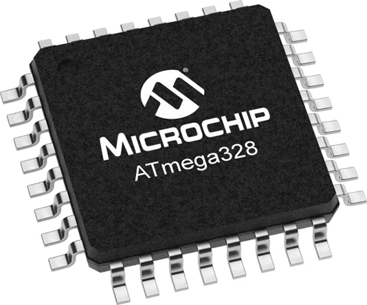
The core of the project is the ATmega328P, an 8-bit AVR RISC-based microcontroller. It features:
- 32 KB flash memory, 1 KB EEPROM, and 2 KB SRAM.
- 23 I/O pins, 3 timers, and a 6-channel 10-bit ADC.
- Operates between 1.8V and 5.5V with up to 1 MIPS/MHz performance.
The microcontroller has three ports:
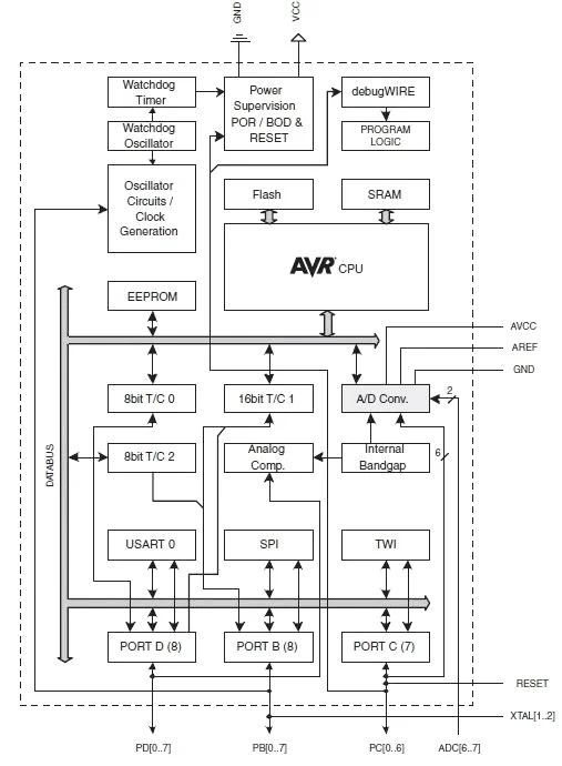
- Port B: 8-bit I/O, supports oscillator and timer functionality.
- Port C: 7-bit I/O, includes a reset pin (PC6).
- Port D: 8-bit I/O with symmetrical drive capabilities.
By default, the ATmega328P uses an internal oscillator but supports an external crystal for better precision and reliability.
PC6/RESET If the RSTDISBL fuse is programmed, PC6 is used as an input pin. If the RSTDISBL fuse is unprogrammed, PC6 is used as a reset input. A low level on this pin for longer than the minimum pulse length will generate a reset, even if the clock is not running.
AVCC is the supply voltage pin for the A/D converter, PC3:0, and ADC7:6. It should be externally connected to VCC, even if the ADC is not used. If the ADC is used, it should be connected to VCC through a low-pass filter. Note that PC6..4 uses digital supply voltage, VCC.
2. CH340 Programmer
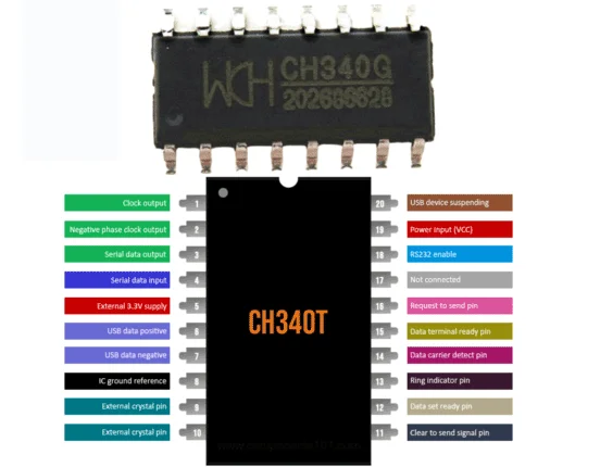
A USB-to-UART conversion chip for programming the microcontroller. Key features include:
- Baud rate: 2400bps to 115200bps.
- Compatible with Arduino IDE, Windows, macOS, Linux, and Android.
- Available with internal or external crystal oscillators.
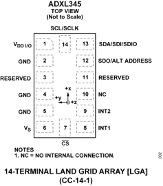
3. ADXL345 Accelerometer
A 3-axis accelerometer for motion and tilt sensing. Highlights:
- Measures up to ±16g with 13-bit resolution.
- Supports SPI and I2C interfaces.
- Built-in features: activity detection, free-fall sensing, and tap recognition.
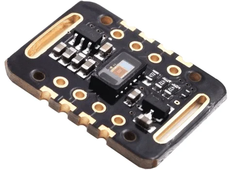
4. MAX30102 Pulse Sensor
An all-in-one module for heart rate and oxygen level monitoring. Features:
- Integrated LEDs and photodetectors.
- Ultra-low power consumption with programmable sampling.
- Compact design (5.6mm x 3.3mm x 1.55mm).
5. SHT21 Humidity and Temperature Sensor
A digital sensor for environmental monitoring. Specifications:
- Temperature accuracy: ±0.3°C.
- Humidity range: 0–100% RH.
- Operates up to 125°C with a max voltage of 3.6V.
6. AMS1117 Voltage Regulator
Ensures stable power supply for the components. Features: Output: 3.3V, max current: 1A. Short circuit and thermal overload protection.
Circuit Schematic and PCB for the Fitness Tracker
The circuit has been designed in KICAD EDA software.
The 3D PCB images of the fitness tracker project are shown below.
Coding and Explanations
The PCB design compactly organizes components, optimizing space and minimizing interference. The layout includes labeled connectors for the DHT11 sensor, ESP32 module, and power supply.
Code for ESP32 MQTT Temperature Monitoring
#include
#include
#include "ADXL345.h" // Accelerometer library
#include "MAX30102.h" // Heart rate sensor library
#include "MLX90614.h" // Body temperature sensor library
// OLED configuration
#define SCREEN_WIDTH 128
#define SCREEN_HEIGHT 64
Adafruit_SSD1306 oled(SCREEN_WIDTH, SCREEN_HEIGHT, &Wire, -1);
// Sensors
ADXL345 accelerometer;
MAX30102 heartRateSensor;
MLX90614 temperatureSensor;
// Variables for storing sensor data
int stepCount = 0;
int heartRate = 0;
float bodyTemperature = 0.0;
void setup() {
// Initialize serial communication
Serial.begin(9600);
// Initialize OLED display
if (!oled.begin(SSD1306_I2C_ADDRESS, 0x3C)) {
Serial.println("OLED initialization failed!");
while (1);
}
oled.clearDisplay();
oled.setTextSize(1);
oled.setTextColor(WHITE);
// Initialize sensors
if (!accelerometer.begin()) {
Serial.println("ADXL345 initialization failed!");
while (1);
}
if (!heartRateSensor.begin()) {
Serial.println("MAX30102 initialization failed!");
while (1);
}
if (!temperatureSensor.begin()) {
Serial.println("MLX90614 initialization failed!");
while (1);
}
// Display startup message
oled.setCursor(0, 0);
oled.println("Initializing...");
oled.display();
delay(2000);
}
void loop() {
// Read data from sensors
stepCount = accelerometer.readSteps();
heartRate = heartRateSensor.getHeartRate();
bodyTemperature = temperatureSensor.readObjectTempC();
// Process data (example: algorithm to evaluate overall activity level)
String activityLevel = evaluateActivityLevel(stepCount, heartRate, bodyTemperature);
// Display data on OLED
oled.clearDisplay();
oled.setCursor(0, 0);
oled.println("Fitness Tracker");
oled.println("----------------");
oled.setCursor(0, 20);
oled.print("Steps: ");
oled.println(stepCount);
oled.print("Heart Rate: ");
oled.print(heartRate);
oled.println(" bpm");
oled.print("Temp: ");
oled.print(bodyTemperature, 1);
oled.println(" C");
oled.print("Activity: ");
oled.println(activityLevel);
oled.display();
// Debugging output
Serial.print("Steps: ");
Serial.print(stepCount);
Serial.print(", Heart Rate: ");
Serial.print(heartRate);
Serial.print(", Temp: ");
Serial.println(bodyTemperature);
delay(1000); // Update every second
}
String evaluateActivityLevel(int steps, int hr, float temp) {
if (steps > 1000 && hr > 120) {
return "Active";
} else if (steps > 500 || (hr > 100 && temp < 37.5)) {
return "Moderate";
} else {
return "Low";
}
}
Let's break the code explanation section block by block to clarify its functionality in the firmware of the fitness tracker.
Block 1: System Initialization
This block is responsible for preparing the microcontroller and peripherals (OLED display, sensors, and push buttons) for operation.
void setup() {
initOLED(); // Initializes the OLED display for output.
initADXL345(); // Configures the accelerometer for motion detection.
initMAX30102(); // Sets up the heart rate and SpO2 sensor.
pinMode(buttonPin, INPUT_PULLUP); // Configures the push button pin as an input with a pull-up resistor.
}
Explanation:
initOLED, initADXL345, and initMAX30102: These functions set up the necessary communication protocols (e.g., I2C) and ensure that the hardware components are ready to operate.
pinMode: The button pin is configured as an input. Using an internal pull-up resistor ensures the button reads a stable HIGH state when not pressed.
Block 2: Data Acquisition
This block reads sensor data and processes it for display.
void collectData() {
int steps = readStepsFromADXL345(); // Fetches step count from the accelerometer.
int heartRate = readHeartRateFromMAX30102(); // Reads heart rate data from the pulse sensor.
displayData(steps, heartRate); // Sends the collected data to the OLED display for visualization.
}
Explanation:
readStepsFromADXL345: This function retrieves the number of steps detected by the accelerometer, which is processed internally to identify motion patterns.
readHeartRateFromMAX30102: This function calculates the user's heart rate using data from the MAX30102 sensor.
displayData: The function updates the OLED display with the latest sensor readings.
Block 3: Data Visualization
This block handles the real-time presentation of data on the OLED display.
void displayData(int steps, int heartRate) {
clearOLED(); // Clears the display to refresh data.
printToOLED("Steps: " + String(steps)); // Displays the step count on the screen.
printToOLED("Heart Rate: " + String(heartRate)); // Displays the heart rate on the screen.
}
Explanation:
clearOLED: Prepares the OLED for new data by erasing the previous output.
printToOLED: Formats and sends text to the display. Here, it shows the number of steps and the heart rate.
Block 4: User Interaction
This block defines how the device reacts to user input, such as resetting data or performing continuous operations.
void loop() {
if (digitalRead(buttonPin) == LOW) { // Checks if the button is pressed.
resetData(); // Resets all collected data to zero.
}
collectData(); // Continuously reads and displays sensor data.
}
Explanation:
digitalRead(buttonPin): Reads the state of the push button. When pressed, it triggers a reset operation.
resetData: Clears stored sensor data (e.g., step count and heart rate).
collectData: Ensures the device operates in real-time by continuously collecting and updating data.
Code for Graphis and visualization of data on OLED:
import processing.serial.*;
Serial myPort; // Create an object for serial communication
int[] stepsData = new int[100]; // Array to store step count history
int[] heartRateData = new int[100]; // Array to store heart rate history
int maxSteps = 200; // Maximum expected step count for graph scaling
int maxHeartRate = 150; // Maximum heart rate for graph scaling
void setup() {
size(800, 400); // Set the window size
myPort = new Serial(this, "COM3", 9600); // Change "COM3" to the port connected to your tracker
myPort.bufferUntil('\n'); // Read data until newline character
}
void draw() {
background(0); // Black background
drawGraph(50, 50, 700, 150, stepsData, maxSteps, color(0, 255, 0), "Steps");
drawGraph(50, 250, 700, 150, heartRateData, maxHeartRate, color(255, 0, 0), "Heart Rate");
}
// Function to draw a graph
void drawGraph(int x, int y, int w, int h, int[] data, int maxVal, color lineColor, String label) {
fill(255);
textAlign(LEFT);
text(label, x, y - 10); // Label the graph
noFill();
stroke(lineColor);
beginShape();
for (int i = 0; i < data.length; i++) {
float xPos = map(i, 0, data.length, x, x + w);
float yPos = map(data[i], 0, maxVal, y + h, y); // Invert y-axis for proper graph display
vertex(xPos, yPos);
}
endShape();
// Draw axes
stroke(255);
line(x, y, x, y + h); // Vertical axis
line(x, y + h, x + w, y + h); // Horizontal axis
}
void serialEvent(Serial myPort) {
String data = myPort.readStringUntil('\n'); // Read incoming data
if (data != null) {
data = trim(data); // Clean up the data
String[] values = split(data, ','); // Assuming data is sent as "steps,heartRate"
if (values.length == 2) {
int steps = int(values[0]);
int heartRate = int(values[1]);
// Shift and update step count history
arrayCopy(stepsData, 1, stepsData, 0, stepsData.length - 1);
stepsData[stepsData.length - 1] = steps;
// Shift and update heart rate history
arrayCopy(heartRateData, 1, heartRateData, 0, heartRateData.length - 1);
heartRateData[heartRateData.length - 1] = heartRate;
}
}
}
Working--
Serial communication:
The microcontroller sends step count and heart rate data in the format steps,heartRate\n via the serial port.
Processing reads this data and splits it into steps and heart rate.
Graph drawing:
Two graphs are drawn: Step graph (green line). Heart rate graph (red line).
Each graph dynamically updates by shifting old data and adding new readings.
Visualization:
Axes are scaled based on predefined maximum values (maxSteps and maxHeartRate).
Labels (Steps, Heart Rate) are displayed above the respective graphs.
Customization:
Adjust size() for different window dimensions.
Update the COM3 port and baud rate (9600) to match your microcontroller settings.
Modify maxSteps and maxHeartRate based on expected sensor output.
One feature of this fitness tracker is that it is offline and visualizes the data on the OLED instead of the cloud. So it costs low and its PCB remains in two layers. You can further integrate it with a BLE module or WiFi for wireless communication.
With further improvements in the code and integration some machine learning models or using better processing graphics code, it will be better in visualization and calculations.
One-stop IoT PCBA and Box-build Manufacturer PCBONLINE for Fitness Trackers
If you want to develop and manufacture any fitness tracker under your brand or your company name, work with the one-stop IoT PCBA manufacturer PCBONLINE with R&D and turnkey electronics manufacturing under one roof.

Founded in 1999, PCBONLINE has two large advanced PCB manufacturing bases, one PCB assembly factory, stable supply chains, and an R&D team. Besides, it has long-term cooperation with China's top 3 mold and enclosure factories for jigs and enclosures for PCB assembly and box-builds. What's more, PCBONLINE has strategic cooperation with mainstream microcontroller companies such as Espressif and Quectel.
PCBONLINE provides free design for manufacturing (DFM) and one-on-one engineering support for fitness trackers and any IoT projects.
PCBONLINE has IoT project R&D capabilities and can do the R&D for your fitness tracker project or take part in your project's development from the early stage.
No worries about programming the MCU, as the one-stop PCBA manufacturer PCBONLINE offers free IC programming for you.
The IoT PCBs, PCBAs, and box-builds at PCBONLINE have gone through comprehensive tests, such as functional testing, 3D AOI, and application simulation testing.
High-quality IoT PCBA manufacturing certified with ISO 9001:2015, ISO 14001:2015, IATF 16949:2016, RoHS, REACH, UL, and IPC-A-610 Class 2/3.
There are clients who have their fitness tracker R&D and one-stop PCBA and box-build assembly from PCBONLINE. When your fitness tracker and any other IOT project go to bulky production, PCBONLINE refunds the fees of R&D, sampling, and PCBA functional testing. To get a quote for your MQTT IoT PCBA project, contact info@pcbonline.com.
Conclusion
This article shows an example project of a simple fitness tracker, including the components used and the Printed Circuit Board using the AVR microcontroller. To develop and manufacture fitness trackers and any other IoT devices, work with experienced experts like PCBONLINE to provide one-on-one engineering support and turnkey manufacturing.
PCB assembly at PCBONLINE.pdf


