
How printed circuit boards (PCBs) are securely handled during PCB assembly, preventing damage to delicate components? PCB edge rails ensure safe and efficient board handling throughout the PCB assembly process.
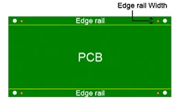
In PCB design, edge rails are added to a PCB to provide space for handling and securely holding the panel during the PCB assembly process. They prevent damage to the components near the board edges and facilitate easy separation (depaneling) of individual PCBs after assembly is complete.
In this article:
Part 1. What are Edge Rails in PCBs? Part 2. How Are Edge Rails Made? Part 3. Best Practices for Designing Edge Rails in PCBs One-Stop Advanced PCB Manufacturing and AssemblyWhat are Edge Rails in PCBs?
Edge rails are integral structural and functional components incorporated into PCBs. Also known as a breakaway rail, it is a rail at the edge of a PCB panel board to fix the board on machines of the SMT (surface-mount technology) assembly line.
Edge rails are primarily designed to extend or augment the edges of the PCB, thereby improving PCB manufacturing processes, handling, and connectivity. They play a vital role in maintaining stability during PCB SMT assembly, enhancing connection quality, and meeting specific design criteria.
One of the important functions of PCB edge rails is to provide support for penalization and depenalization.
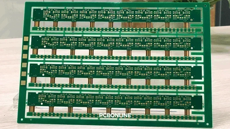
Let's see why penalization is needed in PCB fabrication. In PCB manufacturing and assembly, CNC machines are widely used because they enable large sizes of PCBs. However, electronic products require smaller PCBs. To optimize the efficiency of CNC machines, a single PCB design is often replicated multiple times (e.g., 10 copies) and then processed as a single unit. This technique is known as PCB penalization, and the resulting board is referred to as a PCB panel. A PCB panel with four rigid-flex PCB replicas is demonstrated in the next figure.
After PCB fabrication, the PCB panel is surface-mounted and through-hole-mounted with all the components. Then the PCBA manufacturers should separate the PCBAs from the PCB panel. With the edge rails, the components and the PCB board won't be damaged during depanelization.
Edge rails fulfill several essential roles in PCB manufacturing, assembly, and PCB depaneling:
Support for penalization: Edge rails add material to the PCB panel edges, facilitating panelized manufacturing techniques such as pick-and-place assembly and wave soldering.
Enhanced stiffness and stability: They provide structural reinforcement, particularly for delicate or thin PCBs, preventing warping or deformation during processing.
Connector interfaces: Edge rails can accommodate plating or alignment for edge connectors (such as gold fingers), ensuring proper connectivity.
Routing clearance: They create sufficient space between the functional areas of the PCB and its edges, minimizing the risk of damage during cutting, handling, or transportation.
How Are Edge Rails Made?
Edge rails are made by extending the PCB panel beyond the actual board design, adding extra material along the edges. The exact dimensions of edge rails are subject to variation based on PCB design specifications, assembly methods, and equipment tolerances. Below are the standard parameters:
Thickness of edge rails: Generally, the thickness of edge rails corresponds to that of the PCB itself. Standard PCB thicknesses include: 0.8 mm (31 mils) – Suitable for lightweight designs. 1.6 mm (63 mils) – Commonly used for most PCBs. 2.4 mm (94 mils) – Appropriate for heavy-duty boards or those requiring enhanced mechanical stability.
Height (width) of edge rails: The width of edge rails varies according to specific requirements. 3 mm to 5 mm is typically used for smaller PCBs. While 5 mm to 10 mm is employed for larger or more complex PCBs, ensuring adequate support during assembly.
Material of edge rails: Edge rails are typically made of the same material as the PCB itself, ensuring uniformity and compatibility. Some common materials are FR-4 (Flame Retardant 4), polyimide, and metal core PCBs depending upon the application.
In PCB fabrication, the edge rails are typically made by V-cut – cutting a shallow groove into the edges of the PCB panel to separate the circuit board from the panel. The methods for creating edge rails are below.
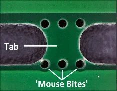
Mouse bites (breakaway tabs)
Drilling small holes is used for detaching PCBs from the panel. The mouse bites consist of small perforations along the edge rail to allow easy snapping of the PCB as shown in the next figure. These are ideal for printed circuit boards that need to be manually separated after assembly.
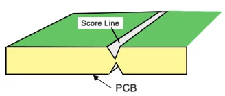
V-cut (V-Scoring)
A shallow, V-shaped cut along the PCB edge allows boards to be snapped apart and is referred to as V-scoring. This feature of edge rail is used for straight-line separations. A V-groove is shown in the following image.
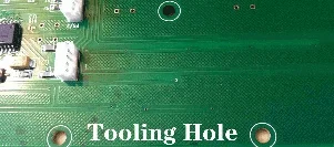
Tooling holes
Tooling holes are drilled in the edge rails to fix the PCB panel onto the machines. The common diameters of these holes are 2mm or 3mm, depending on the manufacturer.
Best Practices for Designing Edge Rails in PCBs
By following these best practices, you can reduce assembly defects and improve depaneling efficiency.
Maintain proper clearanceTo maintain proper clearance, you need to ensure a minimum 1.0–2.0 mm spacing between components and the PCB edge to prevent damages during handling and depaneling. Defining keep-out zones of 2–3 mm to avoid placing critical traces near the edges will also be helpful for the assembly process.
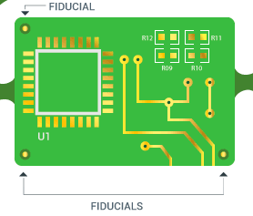
Use alignment featuresIncorporating fiducial markers, tooling holes, or alignment pins to ensure accurate positioning in automated assembly and testing is critical in PCB manufacturing. You need to use at least three fiducials per panel (one in each corner), with a 1.0 mm diameter and a 2.0 mm clearance from copper or silkscreen as shown in the next figure.
To facilitate smooth separation of PCBs after assembly, use:
- V-cuts: A 30°–45° cutting angle with a 0.3mm–0.5mm web thickness for easy snapping.
- Mouse bites: Perforated holes for a controlled breakaway.
- Tab-routing: Ensure a 0.8mm–1.2mm tab width to prevent excessive mechanical stress while keeping structural integrity.
For designs with edge connectors, precise dimensional accuracy is essential to maintain.
Follow manufacturer guidelinesEach PCB manufacturer has specific requirements for edge rail dimensions, V-cut depths, and depaneling techniques. Typically, the edge rail widths range from 5.0mm–10.0mm, ensuring compatibility with conveyor systems and depaneling machines.
When designing the PCB edge rails, you should avoid these common mistakes:
- Keeping inadequate rail width can make panel handling difficult or cause instability during assembly.
- Forgetting to add fiducial marks can lead to misaligned components during assembly.
- Placing components or traces too close to breakaway tabs can lead to damage during separation.
- Different manufacturers may have unique requirements for edge rail width, fiducial placement, or tooling hole sizes, therefore meeting these requirements is critical.
One-Stop Advanced PCB Manufacturing and Assembly
No worries about PCB edge rail design and PCB assembly requirements anymore. You can work with the one-stop PCBA manufacturer PCBONLINE including R&D for turnkey electronics until you receive the final products.
The PCB OEM manufacturer PCBONLINE has two large advanced PCB manufacturing bases, one EMS PCB assembly factory, an R&D team, and stable supply chains. Besides, it has long-term cooperation with the top 3 mold manufacturers in China to manufacture the enclosures for box build assembly and SMT stencils, jigs, and molds for PCB assembly. What's more, it has strategic cooperation with the MCU manufacturers like Espressif, Neoway, Quectel, etc.
PCBONLINE has R&D capabilities and provides free DFM and one-on-one engineering support throughout the PCB OEM project.
One-stop OEM PCB manufacturing custom meeting your project's demands, covering hardware and software R&D, prototyping/sampling, PCB fabrication, component sourcing, PCB assembly, value-added, and box-build assembly.
PCBONLINE offers free prototypes/samples, as well as R&D and PCBA functional testing for mass production OEM PCB projects.
High-quality OEM PCB manufacturing certified with ISO 9001:2015, ISO 14001:2015, IATF 16949:2016, RoHS, REACH, UL, and IPC-A-610 Class 2/3.
PCBONLINE will ensure the success of your project, solve all issues, and provide smooth OEM PCB manufacturing.
No matter what application your project will be used for, such as automotive, industrial control, medical, military, aerospace, communication, computer, etc, you can work with PCBONLINE. To reach out to the OEM PCB manufacturer PCBONLINE, contact info@pcbonline.com.
Conclusion
Edge rails are an essential design feature in PCB manufacturing that provides structural support and enables efficient depaneling. Following the best practices to add edge rails ensures a seamless assembly process, ultimately, contributing to improved production quality and reduced defects of PCBs in various electronic applications. To ensure the success of your PCB and PCBA projects and for one-stop manufacturing, work with the OEM PCB manufacturer PCBONLINE.
PCB assembly at PCBONLINE.pdf


