
Home automation using Arduino, a relay, and a Bluetooth module is a popular project. It allows you to control various electrical devices in a home wirelessly. In a home automation project using Arduino, relay, and Bluetooth module, the Arduino board acts as the main controller, the relay modules are used to switch the devices on and off, and the Bluetooth module provides the wireless communication interface.
Circuit Diagram
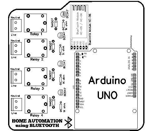
The circuit diagram of Home Automation using Arduino, Relay, and Bluetooth Modules is shown in the figure below. Arduino is our main controller here where we have interfaced Relay and Bluetooth Module.
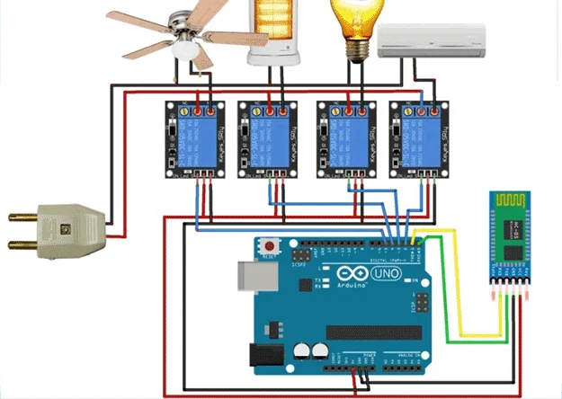
circuit diagram of Home Automation using Arduino, Relay, and Bluetooth Module
Interfacing with HC-05 Bluetooth Module
An HC-05 Bluetooth module is a small portable device that is used to be connected to the Arduino board. It can communicate with mobile or smartphone. It has 6 pins, among which we are concerned with only 4 pins.
Pin of HC-05 Bluetooth Module:
- PIN 2 (RXD for receiving information from a smartphone through Bluetooth medium)
- PIN 3 (TXD for transmitting information from a smartphone through Bluetooth medium)
- PIN 4 (GND for grounding or zero potential point)
- PIN 5 (VCC for the supply of 5 Volt to power up HC-05)
The TXD pin of Arduino is connected to RXD pin HC-05 and the RXD pin of Arduino is connected to the TXD pin of HC-05.
Here, TXD = 1 in Arduino means transmission of information from Arduino to HC-05. And, RXD=0 in HC-05 means receiving information from from Arduino to HC-05.
Also, TXD = 1 in HC-05 means transmission of information from HC-05 to Arduino. And, RXD=0 in Arduino means receiving information from from HC05 to Arduino.
Interfacing with Relay Module
A relay module for Arduino is one of the most powerful applications for Arduino. It can be used to control both AC and DC devices by simply controlling the relay by giving 5V. A relay is a switch that is operated electrically by an electromagnet.
- Logic GND: This will be connected to GND on your Arduino.
- Input 1 (IN 1): This will be connected to a digital pin(2) on your Arduino, or leave it unconnected if you do not want to use this channel.
- Input 2 (IN 2): This will be connected to the digital pin(3) on your Arduino, or leave it unconnected if you do not want to use this channel.
- Input 3 (IN 3): This will be connected to the digital pin(4) on your Arduino, or leave it unconnected if you do not want to use this channel.
- Input 4 (IN 4): This will be connected to the digital pin(5) on your Arduino, or leave it unconnected if you do not want to use this channel.
- Logic VCC: This will be connected to the 5v pin of the Arduino to power the 4 relay module.
Source Code / Programming
// Pin definitions using constants for better maintainability
const int AC_PIN = 2; // Air Conditioner control pin
const int BULB_PIN = 3; // Bulb control pin
const int HEATER_PIN = 4; // Heater control pin
const int FAN_PIN = 5; // Fan control pin
// Serial command definitions
const char AC_ON = 'a';
const char AC_OFF = 'b';
const char BULB_ON = 'c';
const char BULB_OFF = 'd';
const char HEATER_ON = 'e';
const char HEATER_OFF = 'f';
const char FAN_ON = 'g';
const char FAN_OFF = 'h';
// Variable to store incoming serial data
char command;
void setup() {
// Initialize all pins as outputs
pinMode(AC_PIN, OUTPUT);
pinMode(BULB_PIN, OUTPUT);
pinMode(HEATER_PIN, OUTPUT);
pinMode(FAN_PIN, OUTPUT);
// Set initial state of all devices to OFF
digitalWrite(AC_PIN, LOW);
digitalWrite(BULB_PIN, LOW);
digitalWrite(HEATER_PIN, LOW);
digitalWrite(FAN_PIN, LOW);
// Initialize serial communication
Serial.begin(9600);
// Print welcome message (optional)
Serial.println("Device Control System Ready");
Serial.println("Commands: a/b=AC, c/d=Bulb, e/f=Heater, g/h=Fan");
}
void loop() {
// Check if serial data is available
if (Serial.available() > 0) {
// Read the incoming command
command = Serial.read();
// Process the command
switch (command) {
case AC_ON:
digitalWrite(AC_PIN, HIGH);
Serial.println("AC turned ON");
break;
case AC_OFF:
digitalWrite(AC_PIN, LOW);
Serial.println("AC turned OFF");
break;
case BULB_ON:
digitalWrite(BULB_PIN, HIGH);
Serial.println("Bulb turned ON");
break;
case BULB_OFF:
digitalWrite(BULB_PIN, LOW);
Serial.println("Bulb turned OFF");
break;
case HEATER_ON:
digitalWrite(HEATER_PIN, HIGH);
Serial.println("Heater turned ON");
break;
case HEATER_OFF:
digitalWrite(HEATER_PIN, LOW);
Serial.println("Heater turned OFF");
break;
case FAN_ON:
digitalWrite(FAN_PIN, HIGH);
Serial.println("Fan turned ON");
break;
case FAN_OFF:
digitalWrite(FAN_PIN, LOW);
Serial.println("Fan turned OFF");
break;
default:
Serial.println("Invalid command");
break;
}
}
// Small delay to prevent serial buffer overflow
delay(100);
}
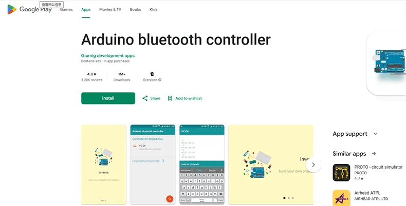
Application Installation
Download and install the app "Arduino Bluetooth controller" or any other Arduino Bluetooth controlling app from Google Play Store to your smartphone and connect it as given below process:
1. Turn on your smartphone Bluetooth
2. Install and open the app
3. Click on connect to Bluetooth
4. Click on HC-05
5. It will ask code, put code '1234' if it doesn't work then put '0000' if this step doesn't work here then go to step 1 and try to connect manually with the same codes, and then follow from step 2.
6. Press OK or Connect and now you are done
Commands from Smart Phone After Bluetooth Connection
- a = AC ON
- b = AC OFF
- c = BULB ON
- d = BULB OFF
- e = HEATER ON
- f = HEATER OFF
- g = FAN ON
- h = FAN OFF
Schematic Diagram
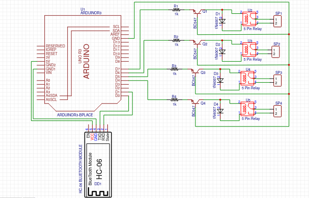
hematic diagram of home automation using Arduino
Arduino & HC-05 communication -
- Date flow: Arduino TX → HC-05 RXD (for sending data), Arduino RX ← HC-05 TXD (for receiving data)
- Power supply: HC-05 gets its 5V and ground directly from the Arduino.
Arduino & Relay connections -
- Control signals: Digital pins (e.g., 2–5) from the Arduino connect to the relay module's inputs (IN1–IN4) to control each relay.
- Shared power: Both the Arduino and the relay module use the same 5V and ground lines.
Purpose: The schematic outlines how every component is electrically connected. It ensures the correct flow of data and power, making sure the device works safely and as expected.
PCB Diagram
PCB diagram of home automation using Arduino
Component layout:
- Arduino Uno in the center: Central placement makes accessing all pins easy.
- HC-05 Bluetooth Module nearby: Placed close to the Arduino's TX/RX pins, which shortens the connection and improves signal quality.
- Relay Module at the edge: This keeps high-voltage circuits (220V) separate from the low-voltage (5V) parts for safety.
Trace routing:
- Power traces (5V, GND): Made wider to safely carry higher currents.
- Signal traces: Kept short and direct to minimize electrical noise.
Key design features:
- Isolation: The layout physically separates high-voltage and low-voltage sections, reducing interference.
- Ground plane: A continuous copper layer stabilizes the circuit and cuts down on electromagnetic interference.
Purpose: The PCB design turns the schematic into a practical, manufacturable board that is both reliable and safe.
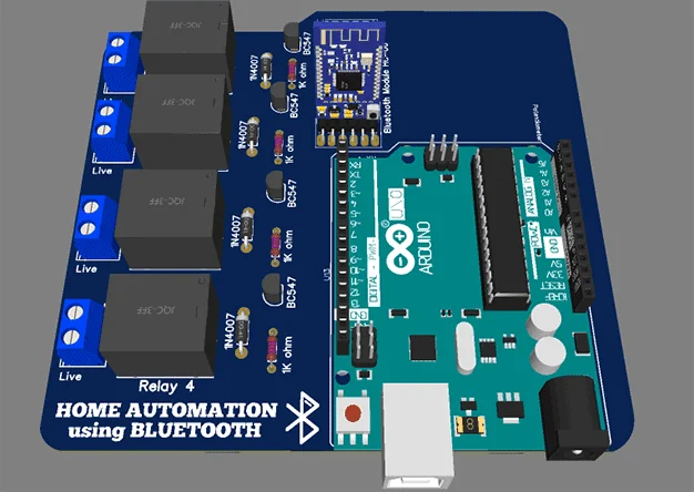
3D Diagram
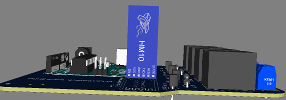
3D diagram of home automation using Arduino
One-stop PCBA Manufacturer for Commercial and Industrial Automation
No matter what your automation project is, if you are from a terminal company, solution company, research institute, or business maker, you can work with the industrial-grade control PCBA manufacturer PCBONLINE for commercial and industrial automation under one roof. In commercial and industrial automation fields, PCBONLINE has powerful electronic manufacturing capabilities:
- Two large advanced PCB manufacturing bases for commercial and industrial automation PCBs,
- One turnkey PCB assembly factory for automation PCB assembly and box-build assembly,
- Stable material supply chains and strategic cooperation with the mainstream MCU manufacturers for all electronic components,
- Long-term cooperation with the top 3 mold and enclosure manufacturers in China for jigs/textures, molds, and enclosures.
- An R&D team and professional CAM engineers for project development and DFM (design for manufacturing).
PCBONLINE offers free DFM before and during commercial/industrial automation board prototyping/sampling to ensure the success of batch production, including checks of Gerber and BOM, jig/fixture/PCB stencil design, manufacturing process, and testing designs, and solving all issues throughout the project to ensure seamless manufacturing.
PCBONLINE provides or assists R&D for your commercial/industrial automation project, including hardware and software R&D, schematics, PCB design, testing design, and enclosure design.
Completing commercial/industrial automation project EMS custom meeting your demands, including PCB manufacturing, component sourcing, PCB assembly, PCBA value-added and testing/inspections in the post-assembly stage, enclosures, and box-build assembly.
PCBONLINE has advantages in thermal management with thermal path design for commercial/industrial automation, PCB busbars, thick-copper PCBs up to 14oz, copper-core PCBs, ceramic PCBs, etc.
High-quality commercial/industrial automation PCB/PCBA manufacturing meeting your application demands, including ISO 9001:2015, ISO 14001:2015, IATF 16949:2016, RoHS, REACH, UL, IPC-A-610 Class 2/3 and IPC-A-610 Class 2/3.
No matter what quantity you want, we always prioritize quality and provide service and support meeting and exceeding your expectations.
PCBONLINE has rich R&D and EMS manufacturing experience. We have successfully worked on these projects:
light controller,
temperature controller, elevator controller,
solar energy storage controller,
smart meter,
brushless motor control,
signal controller,
rail transportation signal module,
industrial signal timer,
industrial network bridge,
IIoT,
oil/gas control system,
rail transportation electronic control,
bank ATM,
industrial camera,
smart manufacturing/automation,
industrial power supply and inverter,
laser cutting controller,
facial recognition automatic customs clearance,
MCU development,
servo motor control,
lawn mower control,
3D scanner,
laser and soldering equipment.
You can send your R&D and manufacturing request to PCBONLINE. To get a quote for your commercial/industrial automation project, please email info@pcbonline.com.
Conclusion
This blog shows a complete guide to simple home automation using Arduino. The PCBA manufacturer PCBONLINE provides reliable EMS manufacturing for commercial/industrial automation and other applications. To bring your commercial/industrial automation project to life with reliability and cost-effectiveness, work with the EMS PCBA manufacturer PCBONLINE.
PCB assembly at PCBONLINE.pdf


