What is meant by SMD components? How many types do you know about SMD? Why SMD components are popular nowadays? This blog will give you a detailed answer.
1. What are SMD Components?
SMD components (chip components) are electronic components printed on a PCB.
It will use surface mount technology - SMT technology.
The process of mounting and soldering chip components is correctly called the SMT process.
SMD components are one of SMT(Surface Mount Technology) components.
Let's take a look at the main SMD elements used in our modern devices.
Resistors, capacitors, small inductors, diodes, and other components look like ordinary small rectangles.
On large SMD elements, they put a code or numbers to determine their affiliation and denomination.
In the photo below, these elements are marked in a red rectangle.
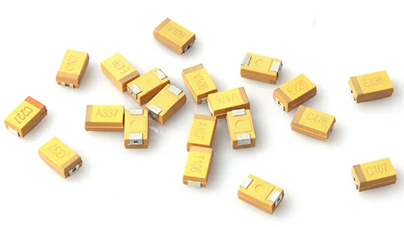
SMD capacitor (tantalum or simply tantalum):

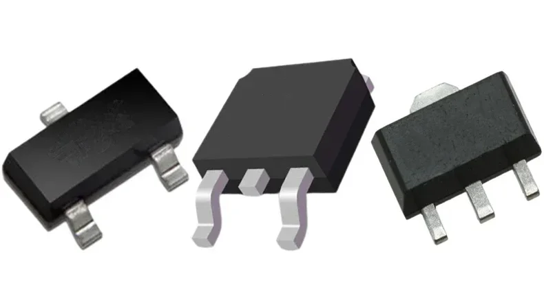
SMD transistors:

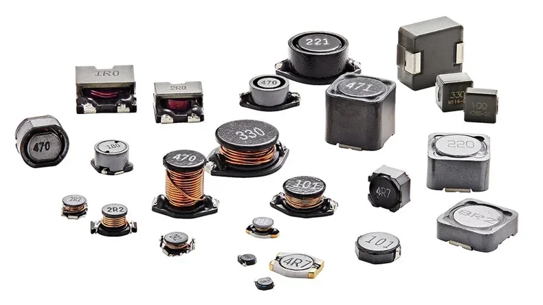
SMD Inductors

2. SMD Components Assembling Process?
SMD components include resistors, capacitors, and microcircuits.
It can be determined based on the dimensions of the element itself.
In the previous lesson, we already got acquainted with the so-called SMD components (chip components). Now it's time to find out how they are installed and soldered by hand and special equipment.
Processes of soldering an SMD part by hand:
Step 1. Apply the solder to one contact pad.
Step 2. Use tweezers, set the chip component to the desired position, and, hold the part with tweezers.
Step 3. Warm up one of the pins and fix it.
Step 4. Solder the second output of the component.
Processes of soldering SMD components and PCBA Process
Step 1. BOM checking
Step 2. Transferring PCBs from automatic loader to solder paste printing machine
Step 3. Printing solder paste onto the PCBs
Step 4. Testing thickness and shape of solder paste
Step 5. Transferring components into the two mounters
Step 6. Placing small components onto the PCBs
Step 7. Placing large components onto the PCBs
Step 8. X-ray inspection and visual inspection
Step 9. Reflow soldering
Step 10. Repeat step 2 to step 9 to mount components on the other side (optional)
Step 11. AOI testing, visual inspection, and sampling inspection
Step 12. Fit long legs of components through PCB holes using DIP
Step 13. Wave soldering
Step 14. Touch-up, cleaning, and visual inspection
Step 15. IC-programming (optional)
Step 16. Functional testing using a PCB tester
Step 17. Aging testing
Due to its small size below are their advantages.
- No need to drill holes for component leads
- Can install components on both sides of the PCB
- High installation density, saving materials
- Cheaper than conventional ones
- Deeper automation of production
3. SMD Components Soldering Defects
Surface mount component defects include:
lower the speed of component assembly
A too-high speed of assembling components, as a rule, provokes a large number of sharp vibrations in the board, which can lead to displacement and even the dropping of components from the board.
Emphasize securing the board during assembly
Board deflection can be eliminated by securing the board with a large number of support pins.
Variables such as thinner or more flexible PCBs and high pressure during installation create the potential for deformation of the PCB during assembly.
Faster lifting of the mounting nozzle allows the curved PCB to abruptly return to its original position, resulting in dropping or other mounting problems.
Check the mounting pressure (pressing force)
If the pressure is correct, check the components for the correct thickness or the correct entry for the thickness of the mounting components.
Excessive pressure when installing open-frame components can lead to the spreading of the solder due to the squeezing of the paste from the contact pads.
Unlike the “headstone” effect, the “billboard” effect is directly dependent on the installation process.
The "billboard" effect is usually seen on passive components such as resistors and capacitors.
Unlike the "headstone" effect, in which one component lead is soldered to the contact pad and the other is not soldered and oriented toward the sky, with the "billboard" effect, both component leads are soldered into the board, but the component is standing vertically on the side ...
If there is a "billboard" effect, you need to check that the coordinates of the component gripping point in the feeder, the feed rate of the components in the feeder, the type of the feeder belt, the absence of obstacles in the path of the component movement, the tolerance for the position of the component or the skew of the feeder belt into the machine for setting the components.
4. What is the Smallest SMD Component?
Manufacturers have placed on the market ever-smaller passive electronic components: for SMD electronic components, however, the right balance must be found between costs and performance.
The passive electronic components not only represent a considerable part of an electronic circuit but also represent one of the areas in which the electronics industry measures its capacity for the miniaturization of SMD technology.
For some years now, companies have been launching smaller and smaller SMD transistors and SMD capacitors on the market of components, to the point of talking about real prodigies of nanotechnologies.
New footprint standards for passive electronic components
Of course, for now, there are only the very minimum dimensions of the latest generation passive electronic components: if the measurements for the SMD capacitors produced today reduce the standard dimensions by 70% (with total dimensions of 0.4 x 0.2mm), the same can also be said for the SMD transistors used in the latest generation smartphones are no exception.
5. What is the Difference between SMT and SMD?
SMT stands for Surface Mount Technology: it, therefore, identifies the technology, the process, which allows you to mount components on the surface of the circuits.
SMD stands for Surface Mounting Device: these are the components that are mounted on the surface of the circuits.
SMT technology was developed in the 1960s but only became popular in the late 1980s. In those years, electronic equipment had electronic boards on which the traditional PTH (Pin through-hole) components were mounted by inserting the terminals of the components themselves in the holes made on the circuits.
The SMT solution offers several advantages:
- 1. Reduced dimensions of the components and therefore of the boards and consequently of the finished product
- 2. Faster assembly thanks to machinery
- 3. Possibility of mounting on both sides of the circuit
- 4. Reduction of the problems that were present with the previous technology, caused by the large distance between traditional components and the PCB (printed circuit)
How to Find a Reliable PCB Components Assembler?
PCBONLINE, an advanced one-stop PCB manufacturer, provides high-end EMS (electronics manufacturing service), including but not limited to advanced PCB manufacturing, assembly, layout service, and component sourcing. It is always dedicated to providing the best PCBs/PCBA and EMS service for our customers. About SMD, PCBONLINE has various channels to source the components for you and also provides suggestions for PCB assembly for free.
Here are reasons to buy PCB Assembly and SMD Components from PCBONLINE:
- We provide a one-stop PCB assembly service for orders without a PCB quantity limit.
- Our SMD components are of high quality and are traceable.
- Our assembly and components are certified with ISO, IATF, REACH, RoHS, and UL standards.
- We offer free first-article inspection to ensure successful SMD component mounting.
- After assembly, we process the functional test and thermal aging test before delivery.
Conclusion
Component assembly requires high Accuracy and stability. If you have read the whole blog you will now be aware of SMD components.
PCBONLINE provides the most comprehensive components, the best SMT equipment, and the most professional Assembly personnel for you. Any type of order or amount is available for assembly if you get in touch with PCBONLNE.


