
In this article, we will design the hardware of the health and location monitoring device. Since the unavailability of WiFi service and other signals can cause problems for data logging on to the server, a modification with long-range communication device integration can be made. This type of data should be real-time in some cases, therefore the lag in signals can cause problems.
However, in this article, we are only discussing the working and hardware designing of an IoT-based person's health and location monitoring device.
This system is built using an ESP32 microcontroller, a GPS module (NEO-6M-V2) for location tracking, a DS18B20 sensor for body temperature measurement, and a pulse sensor for heartbeat monitoring. The collected data is sent to a cloud platform for remote monitoring.
In this article:
Part 1. Metrics to be Measured for Health and Location Monitoring Part 2. Components Used for Health and Location Monitoring Project Part 3: Building the Health and Location Monitoring Device Part 4: PCBA and Box-build Manufacturer for IoT Health Monitoring DevicesMetrics to be Measured for Health and Location Monitoring
Many people suffer from sudden health issues like heart attacks, high fever, and low oxygen levels. If a person is alone or in a remote area, getting immediate medical help becomes difficult. In such cases, a health monitoring device can be life-saving. Also, knowing the person's exact location helps in sending medical assistance quickly.
Temperature and pulse are two fundamental vital signs used to assess a patient's health. So temperature and pulse are the most essential parameters for designing a health monitoring system.
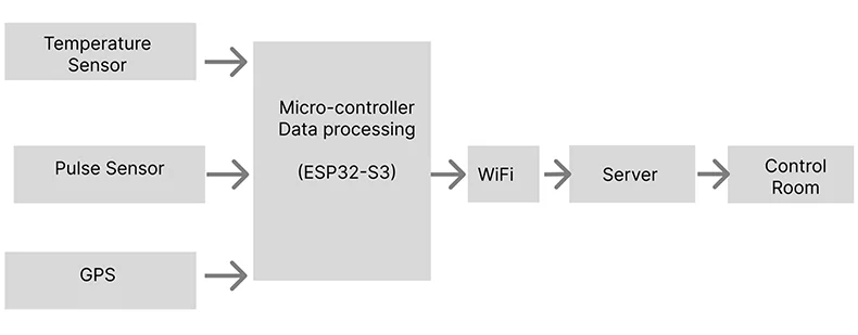
We can design a system using sensors, a microcontroller for data processing, and a back-end/server for data logging. This is an open-loop system where we are only getting values and saving and visualizing these. We are not using feedback to control and sustain the system.
Components Used for Health and Location Monitoring Project
1. Microcontroller
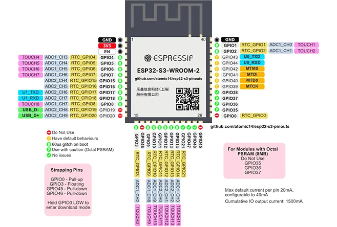
Now we will select the microcontroller. Since it requires the use of WiFi to access the internet therefore we will use the ESP32-S3, which has built-in WiFi as well as Bluetooth. The RAM and CPU specifications are as follows.
CPU and memory:Xtensa® dual-core 32-bit LX7 microprocessor
Clock speed: up to 240 MHz
CoreMark® score:
– One core at 240 MHz: 613.86 CoreMark; 2.56 CoreMark/MHz
– Two cores at 240 MHz: 1181.60 CoreMark; 4.92 CoreMark/MHz
Five-stage pipeline
128-bit data bus and dedicated SIMD instructions
Single precision floating point unit (FPU)
L1 cache
ROM: 384 KB
SRAM: 512 KB
SRAM in RTC: 16 KB
Supported SPI protocols: SPI, Dual SPI, Quad SPI, Octal SPI, QPI, and OPI interfaces that allow connection to flash, external RAM, and other SPI devices
Flash controller with cache is supported
Flash In-Circuit Programming (ICP) is supported
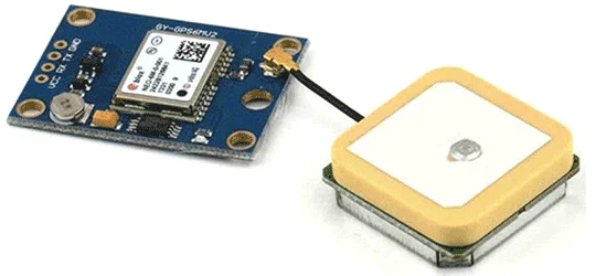
2. GPS module (NEO-6M-V2)
Provides real-time location tracking.
Communicates with ESP32 through UART.
Helps in locating the person when medical help is needed.
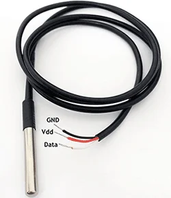
3. DS18B20 temperature sensor
Measures body temperature.
Works with digital communication (1-Wire protocol).
Provides accurate readings with minimal power consumption.
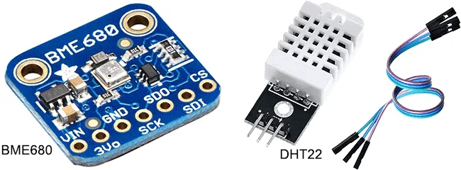
DHT22 vs DS18B20:
|
Specs
|
DHT22
|
BME680
|
DS18b20
|
|
Measure
|
Temperature/Humidity
|
Temperature/Humidity
|
Temp/humi/gass/presseure
|
|
Interface
|
one-wire
|
SPI
|
one-wire
|
|
Voltage
|
3 v-5.5 v
|
1.7 v-3.6 v
|
3v-5.5v
|
|
Interface
|
0 to 50 degree celcius
|
0 to 50 degree celcius
|
-55 to 125 degree celcius
|
|
Temperature
|
+/- 2 degree celcius
|
+/- 0.5 degree celcius
|
+/- 2 degree celcius
|
Above is a comparison of different commonly used sensors. Although the BME680 is more efficient, due to the i2c interface and DS18b20 being simple, we are using this as a temperature sensor.
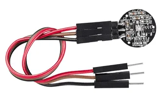
4. Pulse sensor
Measures heart rate by detecting blood flow through the skin.
Gives real-time heart rate data.
Useful for detecting abnormal heartbeat conditions.
This sensor has two surfaces, on the first surface, the light-emitting diode & ambient light sensor is connected. On the second surface, the circuit is connected for noise cancellation & amplification.
The LED is located above a vein like an ear tip or fingertip. Once the LED is located in the vein, the LED starts emitting light.
The ambient light sensor will receive more light if the blood flow is sensed. This small change within obtained light can be examined over time to decide our pulse rates.
Building the Health and Location Monitoring Device
The IoT-based health and location monitoring device continuously tracks health parameters and the person's location. The sensors collect the data and send it to the ESP32 microcontroller. The ESP32 processes this data and sends it to a cloud platform via Wi-Fi. The data can be viewed on a mobile app or web dashboard. If an emergency is detected, alerts can be sent to caregivers or hospitals.
System architecture
The pulse sensor and DS18B20 temperature sensor collect health data.
The GPS module fetches the current location of the person.
The ESP32 processes the data and sends it to a cloud server.
The cloud platform stores and analyzes the data.
The mobile app or web dashboard displays real-time health and location updates.
If an abnormal condition is detected, an alert message is sent to caregivers.
Breadboard prototyping
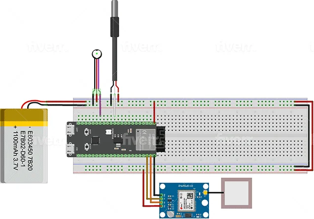
This is the early prototype of the breadboard. There are three sensors for pulse sensing, temperature sensing, and latitude longitudes. It is battery-powered.
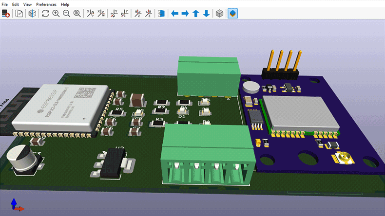
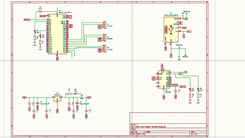
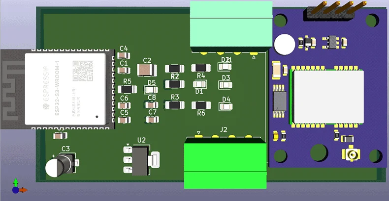
PCB Layout
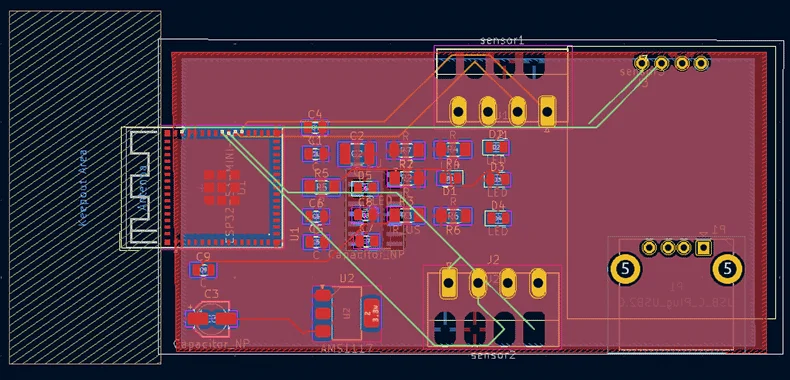
The next step is to design the schematic and PCB layout of the system using KICAD 8.01. The PCB layout has been kept in double 4 layers.
The data will be logged on Google FireBase or ThingSpeak. The data will also be displayed on the onboard OLED (1.3 inches). In this way, one can check the Air Quality data on the device and mobile phone.
Code explanation
Initialize system:
from machine import Pin, ADC
import onewire, ds18x20, time
# Define Temperature Sensor
ds_pin = Pin(4) # GPIO4 for DS18B20
ds_sensor = ds18x20.DS18X20(one wire.OneWire(ds_pin))
# Define Pulse Sensor (Analog)
pulse_sensor = ADC(Pin(34)) # GPIO34 for Pulse Sensor
pulse_sensor.atten(ADC.ATTN_11DB) # Set range (0-3.3V)
Read Temperature Sensor (DS18B20) :
def read_pulse():
pulse_value = pulse_sensor.read() # Read analog value (0-4095)
bpm = (pulse_value / 4095) * 120 # Convert to approximate BPM
return round(bpm)
Read pulse sensor data:
def read_pulse():
pulse_value = pulse_sensor.read() # Read analog value (0-4095)
bpm = (pulse_value / 4095) * 120 # Convert to approximate BPM
return round(bpm)
Process data & print results:
while True:
temperature = read_temperature()
pulse = read_pulse()
print("Temperature:", temperature, "°C")
print("Pulse Rate:", pulse, "BPM")
time.sleep(2) # Delay for stable readings
Features of the system
- real-time health monitoring: continuously measure temperature and heart rate.
- live location tracking: provides the exact location of the person.
- cloud connectivity: data is stored securely and can be accessed from anywhere.
- emergency alerts: sends notifications if abnormal readings are detected.
- low power consumption: uses minimal battery power, making it long-lasting.
- user-friendly: easy to set up and operate.
PCBA and Box-build Manufacturer for IoT Health Monitoring Devices
If you want to develop and manufacture any IoT health and location monitoring devices under your brand or company name, work with the one-stop IoT PCBA manufacturer PCBONLINE with R&D and turnkey electronics manufacturing under one roof.

Founded in 1999, PCBONLINE has two large advanced PCB manufacturing bases, one PCB assembly factory, stable supply chains, and an R&D team. Besides, it has long-term cooperation with China's top 3 mold and enclosure factories for jigs and enclosures for PCB assembly and box-builds. What's more, PCBONLINE has strategic cooperation with mainstream microcontroller companies such as Espressif and Quectel.
PCBONLINE provides free design for manufacturing (DFM) and one-on-one engineering support for IoT health and location monitoring and other IoT projects.
PCBONLINE has IoT project R&D capabilities and can do the R&D for your IoT air quality monitoring project or take part in your project's development from the early stage.
No worries about programming the MCU, as the one-stop PCBA manufacturer PCBONLINE offers free IC programming for you.
The IoT PCBs, PCBAs, and box-builds at PCBONLINE have gone through comprehensive tests, such as functional testing, 3D AOI, and application simulation testing.
High-quality IoT PCBA manufacturing certified with ISO 9001:2015, ISO 14001:2015, IATF 16949:2016, RoHS, REACH, UL, and IPC-A-610 Class 2/3.
When your IoT air quality monitoring and any other IOT project goes to bulky production, PCBONLINE refunds the fees of R&D, sampling, and PCBA functional testing. To get a quote for your IoT air quality monitor PCBA project, contact info@pcbonline.com.
Conclusion
By using the ESP32, GPS, DS18B20, and pulse sensor, the IoT-based system in this article provides an efficient and affordable solution for personal health and safety monitoring. With future improvements, this device can become more powerful and useful for healthcare applications. To develop and manufacture health monitoring devices and any other IoT devices, work with experienced experts like PCBONLINE to provide one-on-one engineering support and turnkey manufacturing.
PCB assembly at PCBONLINE.pdf


