
Programmable Logic Controllers (PLCs) are the workhorses of industrial automation. Their core principles are modularity, deterministic logic, and rugged design. Home PLC projects also use these core principles.
In this blog, for easy understanding, the one-stop industrial control PCBA manufacturer PCBONLINE will walk through PLC project design using a PLC inspired heated floor system for a loggia, complete with Arduino and ESP8266 code, MQTT integration, and industrial-grade PCB design.
Table of contents:
Part 1. What is a PLC? Part 2. Codes for the PLC Heated Floor System Part 3. Industrial PCB Design Tips for PLC Projects Part 4. Safety & Troubleshooting for the PLC Heated Floor System One-stop Industrial Control PCBA Manufacturer for PLC ProjectsWhat is a PLC?
A Programmable Logic Controller (PLC) is important in industrial control fields. A PLC is an industrial computer that automates machinery using a strict scan cycle. Its scan style includes:
- 1. Input scan: Read sensors (temperature, pressure).
- 2. Logic execution: Run control algorithms (e.g., PID).
- 3. Output update: Trigger actuators (relays, motors).
- 4. Communication: Report data to HMIs (Human-Machine Interfaces).
PLCs thrive in harsh environments, thanks to rugged PCBs and EMI shielding. Let's apply the above principles to a heated floor system as an example of the PLC project design.
PLC Heated Floor System Overview
This blog uses a home heated floor system as an example to demonstrate PLC project development.
The components used in this PLC project example are:
- Arduino Nano: Reads DS18B20 sensors and controls relays.
- ESP8266 NodeMCU: Publishes data to MQTT.
- DS18B20: Waterproof temperature sensor (-55°C to +125°C).
- 5V relay: Switches 220V heating mat.
- Power supply: 12V/2A adapter with buck converter (12V→5V).
The workflow of this PLC project example is:
1. Arduino reads outdoor temperature.
2. Applies hysteresis logic (heating ON/OFF).
3. ESP8266 sends data to MQTT for remote monitoring.
Now let's see the wiring diagram of this PLC project example.
|
Component
|
Arduino Nano
|
ESP8266
|
|
DS18B20 (Data)
|
D2
|
–
|
|
Relay (IN1)
|
D7
|
-
|
|
Arduino TX
|
-
|
RX (D6)
|
|
Arduino RX
|
-
|
TX (D5)
|
|
Shared ground
|
GND
|
GND
|
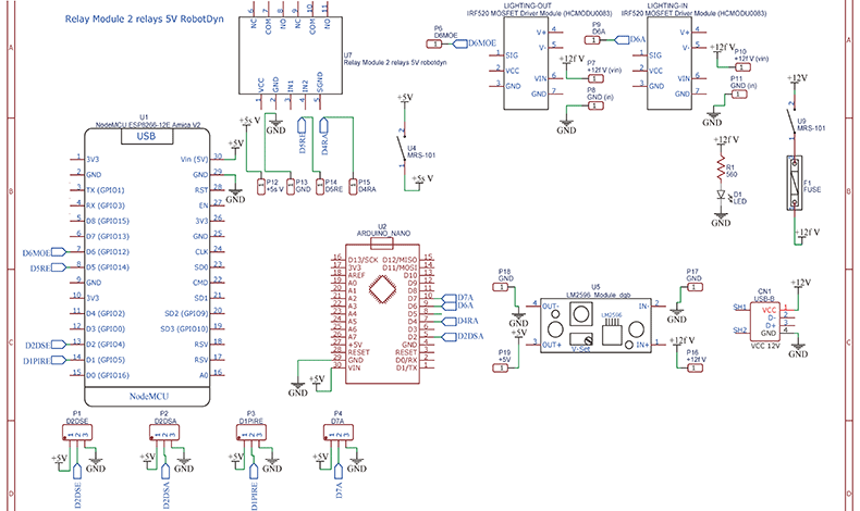
Here's the schematic of this PLC heated floor system for your reference.
Codes for the PLC Heated Floor System
All the codes used for this PLC project example -- a heated floor system and their explanation are below, including the Arduino and ESP8266 using MQTT communication.
Arduino code (sensor & relay control)
The Arduino acts as the PLC CPU, handling sensor reads and relay control.
Complete code:
cpp
Copy
#include
#include
// Pins
#define ONE_WIRE_BUS 2 // DS18B20 on D2
#define RELAY_PIN 7
// Hysteresis Settings
float setpoint = 18.0; // Default threshold
float hysteresis = 2.0; // Prevents relay chattering
OneWire oneWire(ONE_WIRE_BUS);
DallasTemperature sensors(&oneWire);
void setup() {
Serial.begin(115200);
sensors.begin();
pinMode(RELAY_PIN, OUTPUT);
digitalWrite(RELAY_PIN, LOW); // Start with relay OFF
}
void loop() {
// 1. Read Temperature
sensors.requestTemperatures();
float temp = sensors.getTempCByIndex(0);
// 2. Execute Logic (PLC-like Scan Cycle)
if (temp < (setpoint - hysteresis)) {
digitalWrite(RELAY_PIN, HIGH); // Heat ON
} else if (temp > (setpoint + hysteresis)) {
digitalWrite(RELAY_PIN, LOW); // Heat OFF
}
// 3. Send Data to ESP8266 via Serial
Serial.print("TEMP:");
Serial.println(temp);
delay(10000); // 10-second scan cycle
}
// Function to update setpoint via serial
void updateSetpoint(float newSetpoint) {
setpoint = newSetpoint;
}
Code explanation:
- Libraries: OneWire and DallasTemperature for DS18B20 communication.
- Hysteresis logic: Prevents relay flapping (heating ON at 16°C, OFF at 20°C).
- Serial communication: Sends temperature data to ESP8266 in TEMP:18.5 format.
ESP8266 code (MQTT communication)
The ESP8266 handles WiFi, MQTT publishing, and command processing.
Complete code:
cpp
Copy
#include
#include
// WiFi Credentials
const char* ssid = "YOUR_WIFI_SSID";
const char* password = "YOUR_WIFI_PASSWORD";
// MQTT Broker
const char* mqttServer = "192.168.1.100"; // Replace with your broker IP
const int mqttPort = 1883;
const char* mqttUser = "user";
const char* mqttPassword = "pass";
// Topics
const char* pubTopic = "loggia/temperature";
const char* subTopic = "loggia/setpoint";
WiFiClient espClient;
PubSubClient client(espClient);
void setup() {
Serial.begin(115200);
connectWiFi();
client.setServer(mqttServer, mqttPort);
client.setCallback(callback);
}
void loop() {
if (!client.connected()) reconnectMQTT();
client.loop();
// Read temperature from Arduino
if (Serial.available()) {
String data = Serial.readStringUntil('\n');
if (data.startsWith("TEMP:")) {
float temp = data.substring(5).toFloat();
client.publish(pubTopic, String(temp).c_str());
}
}
}
// Handle incoming MQTT messages
void callback(char* topic, byte* payload, unsigned int length) {
String message;
for (int i = 0; i < length; i++) message += (char)payload[i];
if (String(topic) == subTopic) {
float newSetpoint = message.toFloat();
Serial.print("SET:"); // Send new setpoint to Arduino
Serial.println(newSetpoint);
}
}
void connectWiFi() {
WiFi.begin(ssid, password);
while (WiFi.status() != WL_CONNECTED) {
delay(500);
}
}
void reconnectMQTT() {
while (!client.connected()) {
if (client.connect("ESP8266Client", mqttUser, mqttPassword)) {
client.subscribe(subTopic);
} else delay(5000);
}
}
Code explanation:
- MQTT setup: Connects to a broker (e.g., Mosquitto) and subscribes to loggia/setpoint.
- Serial handling: Parses TEMP:18.5 from Arduino and publishes to MQTT.
- Setpoint updates: Forwards new thresholds (e.g., 20.0) to Arduino via serial.
Industrial PCB Design Tips for PLC Projects
To mimic PLC reliability, follow these PCB best practices:
High-current traces:
- Use 2 oz copper for relay/power sections.
- Widen traces (>150 mils) near high-current components.
EMI shielding:
- Add a ground plane beneath the ESP8266.
- Use ferrite beads on power lines.
Thermal management:
- Place thermal vias under the relay.
- Avoid routing sensitive signals near heat sources.
Ruggedization:
- Apply conformal coating to protect against humidity.
- Use screw terminals (not headers) for I/O connections.
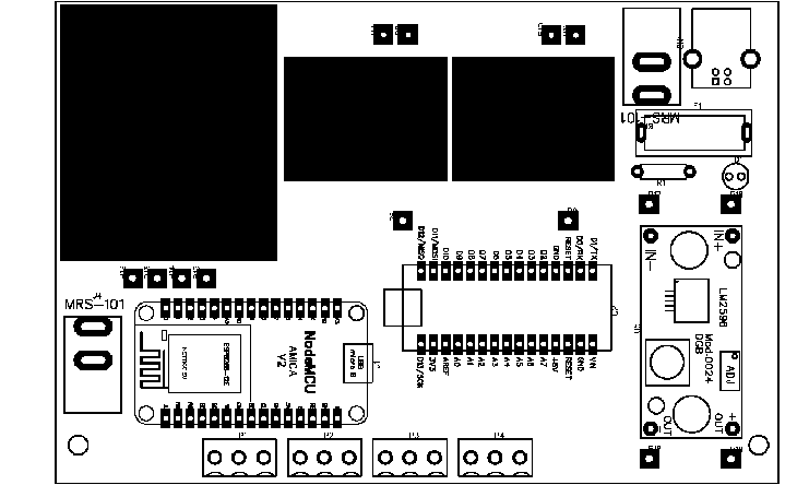
These techniques prove that robust automation doesn't require a factory budget—just smart design. Here's the PCB design for the PLC project example in this blog.
Safety & Troubleshooting for the PLC Heated Floor System
The safety tips for the heated floor system PLC project are:
Use an optocoupler relay to isolate 5V and 220V circuits.
Add a fuse (5A) on the heating mat's live wire.
The common issues in this PLC project example and their solutions are in the table below.
|
Problem
|
Solution
|
|
DS18B20 not detected
|
Check 4.7kΩ pull-up resistor on D2
|
|
ESP8266 WiFi drops
|
Add a capacitor (100µF) near the 3.3V regulator
|
|
Relay chattering
|
Increase hysteresis (e.g., 3°C)
|
By merging PLC principles with affordable hardware, this project brings industrial-grade automation to your loggia. The Arduino and ESP8266 code replicates a PLC's scan cycle, while rugged PCB design ensures reliability.
Next steps to further develop the PLC project example until its box-build assembly in this article are:
- Integrate a PID controller for smoother temperature control.
- Add energy monitoring using an INA219 sensor.
- Encase the system in an IP67-rated enclosure.
One-stop Industrial Control PCBA Manufacturer for PLC Projects
No matter what your PLC project is, including heated floor systems, you can work with the industrial control PCBA manufacturer PCBONLINE for PLC electronics manufacturing services (EMS) under one roof. In industrial control fields, PCBONLINE has powerful electronic manufacturing capabilities:
- Two large advanced PCB manufacturing bases for industrial control PCBs,
- One turnkey PCB assembly factory for PLC PCB assembly and box-build assembly,
- Stable material supply chains and strategic cooperation with the mainstream MCU manufacturers for all electronic components,
- Long-term cooperation with the top 3 mold and enclosure manufacturers in China for jigs/textures, molds, and enclosures.
- An R&D team and professional CAM engineers for project development and DFM (design for manufacturing).

PCBONLINE offers free DFM before and during industrial control board prototyping/sampling to ensure the success of batch production, including checks of Gerber and BOM, jig/fixture/PCB stencil design, manufacturing process and testing designs, and solving all issues throughout the project to ensure seamless manufacturing.
PCBONLINE can provide or assist R&D for your industrial PLC project, including hardware and software R&D, schematics, PCB design, testing design, and enclosure design.
Completing industrial PLC project EMS custom meeting your demands, including PCB manufacturing, component sourcing, PCB assembly, PCBA value-added and testing/inspections in the post-assembly stage, enclosures, and box-build assembly.
PLC projects prioritize thermal management and high-current carrying capabilities. For this, we have advantages in thermal management with thermal path design, PCB pusbars, thick-copper PCBs up to 14oz, copper-core PCBs, and ceramic PCBs, etc.
High-quality industrial PCB/PCBA manufacturing meeting your application demands, including ISO 9001:2015, ISO 14001:2015, IATF 16949:2016, RoHS, REACH, UL, IPC-A-610 Class 2/3 and IPC-A-610 Class 2/3.
No matter what quantity you want, we always prioritize quality and provide service and support meeting and exceeding your expectations.
PCBONLINE has rich R&D and EMS manufacturing experience in industrial control fields like PLC. You can send your R&D and manufacturing request to PCBONLINE. To get a quote for your PLC project, please email info@pcbonline.com.
Conclusion
This blog uses a simple home heated floor system to illustrate the PLC project design principles. However, the PLC PCBA manufacturer PCBONLINE focuses on industrial control PLC and other middle and high-end applications. To bring your PLC project into life with reliability and cost-effectiveness, work with the EMS industrial control PCBA manufacturer PCBONLINE.
PCB assembly at PCBONLINE.pdf


