
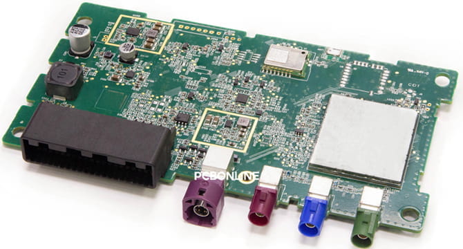
In the industrial control field, the RS485 communication protocol is widely used for industrial automation control, instrumentation, security monitoring, and so on.
How does RS485 communication work? How to apply RS485 communication to your industrial control project? This blog introduces how RS485 communication works and uses a simple project example to reveal how to apply RS485 with ESP32 using the MAX485 module.
In this article:
Part 1. Introduction to RS485 Part 2. How Does RS485 Communication Work? Example: RS485 Communication with ESP32 and MAX485 One-Stop PCBA Manufacturer for RS485 Communication ProjectsIntroduction to RS485
RS485 is a balanced differential serial communication protocol.
It is widely used in industrial automation, embedded systems, and long-distance data transmission.
It supports multiple devices on the same bus and allows for noise-resistant data communication over long distances.
Unlike RS232, which is limited to point-to-point communication, RS485 allows multiple devices to communicate over a single twisted-pair cable.
The RS485 communication protocol has been widely used in industrial control due to its strong anti-interference ability and long transmission distance. The features of the RS485 protocol are:
- Long distance – Supports communication over 1200 meters.
- Multi-device support – Up to 32 devices can be connected on the same bus.
- Noise immunity – Uses differential signaling, reducing electromagnetic interference (EMI).
- Higher speed – Data rates up to 10 Mbps for short distances.
RS485 is widely used in various industries due to its robustness. Some applications include:
- Industrial automation – Used for PLC communication, sensor networks, and motor controllers.
- Smart meters – Used in power grids for smart energy meters.
- Building automation – HVAC systems, security systems, and elevator control use RS485.
- CNC machines – Used in industrial robotics and CNC controllers.
- Agriculture – Used for greenhouse monitoring systems.
How Does RS485 Communication Work?
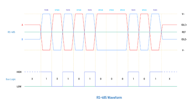
RS485 operates in a half-duplex mode, meaning devices take turns to send and receive data. It uses two differential lines:
A (D+) – Non-inverting
B (D-) – Inverting
When A > B, the signal is logic 1, and when B > A, it's logic 0.
For proper communication, an RS485 transceiver (like the MAX485 module) is used to convert TTL (transistor-transistor logic) signals from a microcontroller (ESP32, Arduino, STM32) to differential signals.
When you set up an RS485 network, choose the right topology so that the RS485 protocol works properly.
The standard and recommended topology for RS485 networks is a daisy chain. The other topology the star chain is discouraged.
- Daisy chain (linear bus): The most common topology for the RS485 communication network, where all devices share the same two-wire RS485 bus.
- Star topology (not recommended): It causes signal reflections and distortion due to mismatched impedance.
The best practice is to always use daisy-chain connections and 120Ω termination resistors at both ends of the RS485 bus for proper impedance matching.
Example: RS485 Communication with ESP32 and MAX485
Below is an application example of RS485 communication with ESP32 and MAX485 modules.
An ESP32 is a powerful WiFi and Bluetooth development board suitable for a variety of embedded systems.
A MAX485 module is an RS485 driver and receiver. It is used in industrial automation, remote sensors, and other occasions requiring long-distance communication.
The components required for this example project are:
- ESP32 development board
- MAX485 RS485 module
- 120Ω termination resistors
- Jumper wires
- Power supply (5V/3.3V)
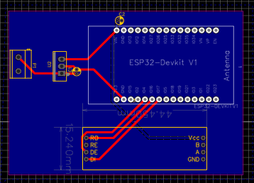
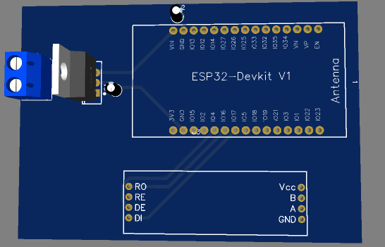
ESP32 RS485 Circuit Diagram
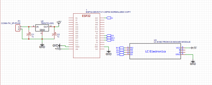
Connections Between ESP32 and MAX485:
|
ESP32 Pin
|
MAX485 Pin
|
Description
|
|
3.3V
|
VCC
|
Power Supply
|
|
GND
|
GND
|
Ground
|
|
GPIO17
|
RO
|
Receiver Output
|
|
GPIO16
|
DI
|
Data Input
|
|
GPIO4
|
RE
|
Receiver Enable
|
|
GPIO5
|
DE
|
Driver Enable
|
⚡ Important:
RE and DE should be controlled together (LOW for receiving, HIGH for transmitting).
A 120Ω resistor is needed at each end of the RS485 network for proper termination.
ESP32 RS485 Transmitter Code
#include
#define TX_PIN 16
#define RX_PIN 17
#define RE_DE 4 // Receiver Enable and Driver Enable
HardwareSerial RS485 ( 1 ) ;
void setup () {
pinMode ( RE_DE, OUTPUT ) ;
digitalWrite ( RE_DE, HIGH ) ; // Set to transmit mode
RS485 . begin ( 9600 , SERIAL_8N1, RX_PIN, TX_PIN ) ;
}
void loop () {
digitalWrite ( RE_DE, HIGH ) ; // Enable transmission
RS485 . println ( "Hello from ESP32 via RS485" ) ;
delay ( 1000 ) ;
}
ESP32 RS485 Receiver Code
#include
#define TX_PIN 16
#define RX_PIN 17
#define RE_DE 4
HardwareSerial RS485 ( 1 ) ;
void setup () {
pinMode ( RE_DE, OUTPUT ) ;
digitalWrite ( RE_DE, LOW ) ; // Set to receive mode
RS485 . begin ( 9600 , SERIAL_8N1, RX_PIN, TX_PIN ) ;
Serial . begin ( 115200 ) ;
}
void loop () {
if ( RS485 . available ()) {
String receivedData = RS485 . readStringUntil ( ' \n ' ) ;
Serial . println ( "Received: " + receivedData ) ;
}
}
RS485 PCB Design Considerations
When designing a PCB for RS485, follow these best practices:
1. PCB Layout for noise reduction
- Keep RS485 traces short to minimize signal degradation.
- Use differential pairs (A and B should run parallel).
- Place a ground plane to reduce EMI.
2. Termination and pull-up resistors
- 120Ω termination resistorsat both ends of the RS485 bus.
- Use pull-up (10kΩ) and pull-down (10kΩ) resistors on A and B lines to prevent floating states.
3. Power supply and protection
- Use decoupling capacitors (100nF) near the MAX485 module.
- Add TVS diodes for surge protection.
4. Isolated RS485 communication
For high-noise environments, YOU can use opto-isolators to isolate ESP32 from RS485 signals.
One-Stop PCBA Manufacturer for RS485 Communication Projects
If you want electronics manufacturing for the RS485 protocol project from R&D to PCBA and box-build assembly, you can work with the one-stop industrial control PCBA manufacturer PCBONLINE.
Found in 1999, PCBONLINE has two large advanced PCB manufacturing bases, one PCB assembly factory, stable supply chains, an R&D team for development, and one-stop PCBA manufacturing for industrial control and embedded systems.
PCBONLINE has R&D capabilities and rich industrial control hardware development experience. We can do the R&D or take part in your project's development from the early stages.
PCBONLINE offers free design for manufacturing (DFM) and one-on-one engineering support and solves all technical issues to ensure the smooth manufacturing process and successful results of your RS485 protocol PCBA project.
One-stop industrial control PCBA manufacturing capabilities custom meeting your requirements, including R&D, prototyping/sampling, PCB fabrication, component sourcing, PCB assembly, PCBA value-added, and box-build assembly.
High-quality industrial control PCBA manufacturing certified with ISO 9001:2015, IATF 16949:2016, REACH (EC 1907/2006), RoHS (Directive 2002/95/EC), and UL.
As a source factory manufacturer for industrial control PCBAs, the electronics manufacturing from PCBONLINE is at reasonable prices without hidden costs.
To get a quote for your industrial control PCBA project with the RS485 protocol, please contact info@pcbonline.com. When your project goes to bulk production, we will refund the fees of R&D, sampling, and PCBA functional testing to you.
Conclusion
RS485 is a powerful, noise-resistant, and long-range communication protocol widely used in industrial and embedded systems. By using an ESP32 with MAX485, you can build multi-device networks for reliable data transmission. To bring your RS485 protocol project into real boards and devices, chat with the one-stop industrial control PCBA manufacturer PCBONLINE from the online chat window.
PCB assembly at PCBONLINE.pdf


